I am developing a mixed-signal embedded system that requires both 5V and 3V rails.
The 5V rail powers an analogue sensor and a precision ADC. The nature of the sensor is such that its output will be DC most of the time and slow-changing the rest of the time. Low noise and low temperature coefficient are the most important aspects of this rail.
The 3V rail supplies the digital circuitry (ADC digital interface, MCU (SPI & UART comms), modem). There are two SPI slaves – the ADC and a DAC. The noise, tempco and regulation of this rail are not critical. Low cost is most important.
The ADC is continuously sampling, the SPI transactions are periodic and the UART communication is on-demand (and infrequent). The microcontroller's internal oscillator runs at 1MHz and is sync'd to a 32768Hz watch crystal.
There needs to be a wide input voltage range (10 – 40V DC). For this reason I intend to use three series LDOs; the first will connect to the input and will output 5.5V. The reason for 5.5V is that the 5V supply has a dropout voltage of 200mV, which needs to be maintained over a large temperature range.
This 5.5V rail will feed the two other LDOs. Two ways of achieving this are shown in the image below (the 40 ohm resistor is integral to an IC – all circuit current flows through it):
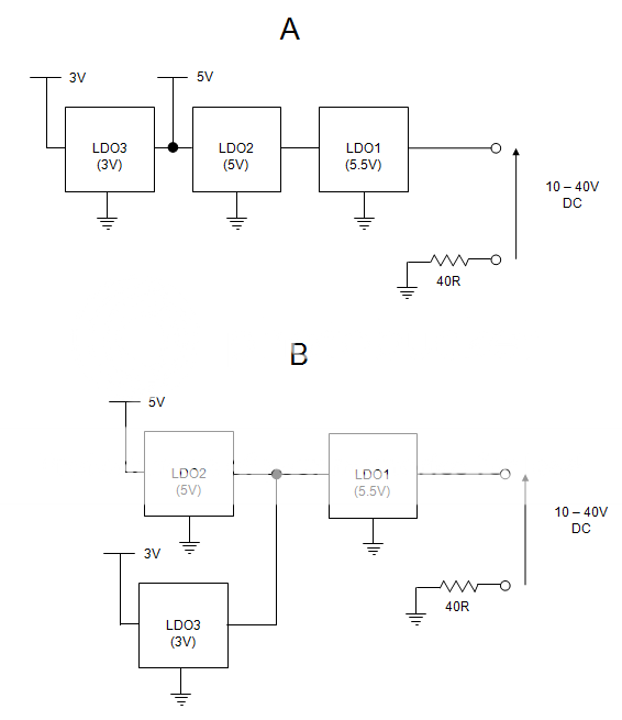
With reference to the image, please evaluate the truth of the following statements:
1) Topology B is much superior, even if the supplies are bypassed well, as changes in demand will still have some effect on the 5V rail load regulation.
2) There is not much difference between topologies A and B, if the supplies are well bypassed and the 5V rail has good load regulation.
3) Statements 1) and 2) can't be meaningfully evaluated without more information about the system and components.
4) The greatest effect by far will be due to the grounding scheme (e.g. daisy-chained ground connections back to the 40 ohm resistor as opposed to a star configuration).
5) Both topologies are a strange/inefficient way of achieving the objective. There are solutions that are much better in terms of cost and performance.
6) This question shows a lack of understanding.
EDIT: 7) LDOs are generally better at dealing with line variation than load variation. So while topology B might have more of an effect on the 5.5V rail, the 5V LDO will handle this better than if there was an effect on its load (as there is in topology A).
EDIT: To clarify, the circuit is low power – only 3.1mA in total is drawn from the input.
Best Answer
B is better- you're not directly injecting digital noise into your precision analog supply.
It might be even better to draw the 3.3V supply directly from the input supply. For example, a single BJT (emitter follower) from the 5.5V regulator will give you a bit under 5V out, which your 3.3V LDO can easily handle (assuming it can't handle 40V directly). That will also reduce the dissipation in the 5.5V LDO (do you really have to call it that close, and do you really need an LDO in this position?).