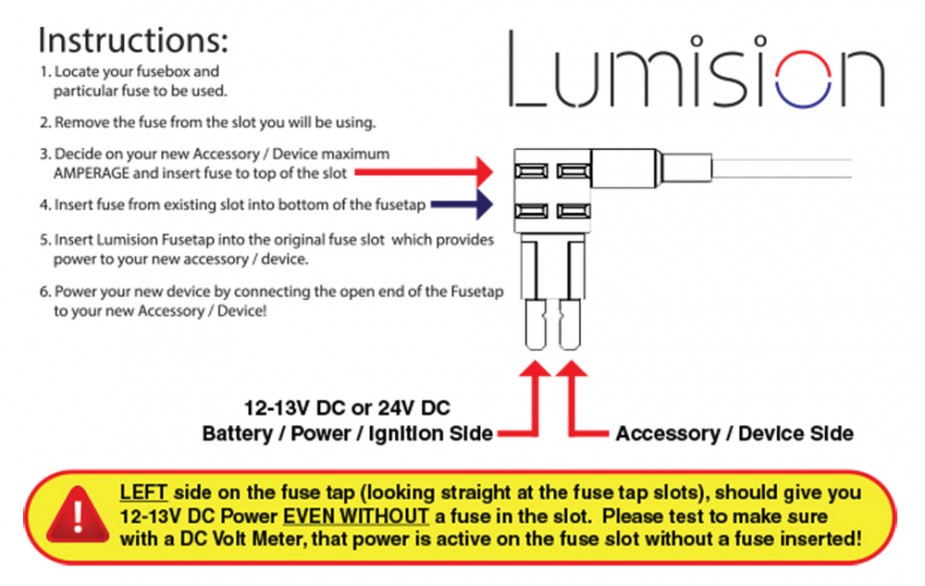
Am looking to use a fuse tap to run a dash cam. These are instructions https://www.lumision.com/wp-content/uploads/2015/09/Micro2-Fuse-Tap-Instructions-e1441486778366.jpg for a fuse tap and consistent with the common recommended way to install. Basically, this shows the fuse tap powering devices on the original circuit and the dash cam in parallel. A more controversial way among dash cam installers is to install the fuse tap in series. That is the power end is switched around. The idea for the latter is it would allow for better protection for the supply wire going into the fuse box.
Can someone who is an electrical engineer comment on the pros and cons of each?
Update/ Follow-on Question (based on answer posted):
I wish to say that I am not an engineer so my level of knowledge is very basic. When you say that there is no benefit, wiring in series does not protect the supply wire? Please confirm. The goal is to avoid an eletrical fire which would entail replacing high dollar auto wiring. The sub $200 dash cam is expendable IMO. If wiring the controbersial way doesnt protect the supply wire then certainly the confusion is not worth it.
Best Answer
Figure 1. The fuse tap instructions.
simulate this circuit – Schematic created using CircuitLab
Figure 2. "Fuse tap" configuration.
I've never heard of these but judging by the illustration it is internally configured as shown in Figure 2. The original fuse, F2, is removed, the tap inserted in its place and F2 inserted in the lower socket in the tap.
F3 is inserted in the top slot to power the dash cam.
All fuses are wired in series with the load. F2 was in series before the tap was added and will be in series after the tap is added.
simulate this circuit
Figure 3. Fuse tap inverted.
If you do as the "controversials" do then both F2 and F3 are in series with the dashcam. This means that if F2 blows you will lose both circuits.
Since F3 should be the smallest size available to protect the camera it would always blow first.
Wire it the correct way to avoid confusion. There is no benefit in wiring in a non-standard way.
After update to question:
Fuses do two things:
Any fuse added in series with the circuit offers protection. The point is that one is enough.
If you are tapping off a 15 A circuit then F2 will be 15 A and F3 will be the smallest available - probably 5 A. If you exceed 5 A on the dashcam which fuse do you think will blow in Figure 3?