thanks for taking the time to read my question. The real question is on the bottom, the context is super simple stuff that should take 2 minutes to read. Please tell me if you need clarification.
I have this 5v to 12v step up converter 
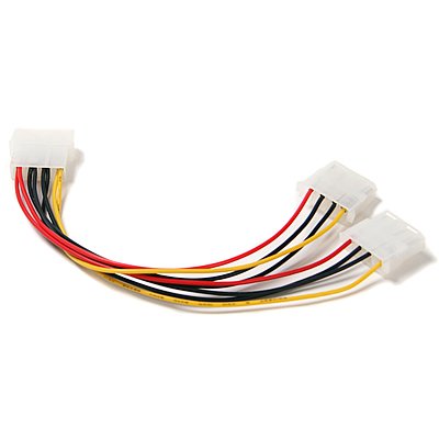
that will convert my power input from 5v to 12 volt; however, I want to directly solder some wires to this converter. As you see, there are two slots for a 12V Power Output in which I can directly solder live wires to. I want to use this molex cable as a Y-Split connection to attach 2 more devices from the power output on the USB stepup, and thus I want to solder the wires on the molex to the step-up converter.
 .
.
However; you might notice that at the start of the Molex cable there are 4 separate pins with 2 wires in each pin. My plan was to cut off the molex connector just described (as I want to solder wires directly onto the USB Step Up module), and then solder those wires right onto the 12V power output.
So here is my question: If I cut off the Molex connector by cutting the wires right before, I expose the two wires coming into 4 separate pins. If I want to solder the wires to the 5v to 12v USB Step up PCB (and receive power output) would I first solder the black and black wires together (I know there are 2 black wires going into 2 separate pins so I should ignore one of the black wires, right?), and the red and red wires together, and then solder the now combined red wire to the positive output and the now combined black wire to the negative output?
OR
Should I de-attach the molex cable to expose the the pins that were in the connector  and solder the pins onto the USB step up converter? I feel like the first way of doing it is better as the pins don't transfer electricity, they are only fitting devices so that the wires attach to the molex vs soldering the wire directly onto the converter.
If you have a better way of soldering, please tell me.
Best Answer
To save doing all of that, I would think it would be much easier if you just went and bought the other part of that Molex lead you have, for it to plug into, then you can just solder 2 wires from your Voltage Converter PCB and then solder them straight to the other Molex socket. Then you can just plug it in any time you want, and you still have your lead in good working order in case you want to use it for another project.
That is the way I would do it anyway.