The SC18IS602B chip is an I2C slave device that bridges to a number of SPI devices. I'm using this to talk to 3 SPI devices that use TLC5925 constant current LED sink drivers. These devices are known good (tested in another setup). The problem I'm trying to solve is that when I send data out of the first SPI port all the LED rings change at once. I have confirmed with a multi-meter that all the slave select (SS[0-2]) lines are high. And using a bus pirate I confirmed they stay high most of the time. Briefly dropping low near the SPI transmission point.
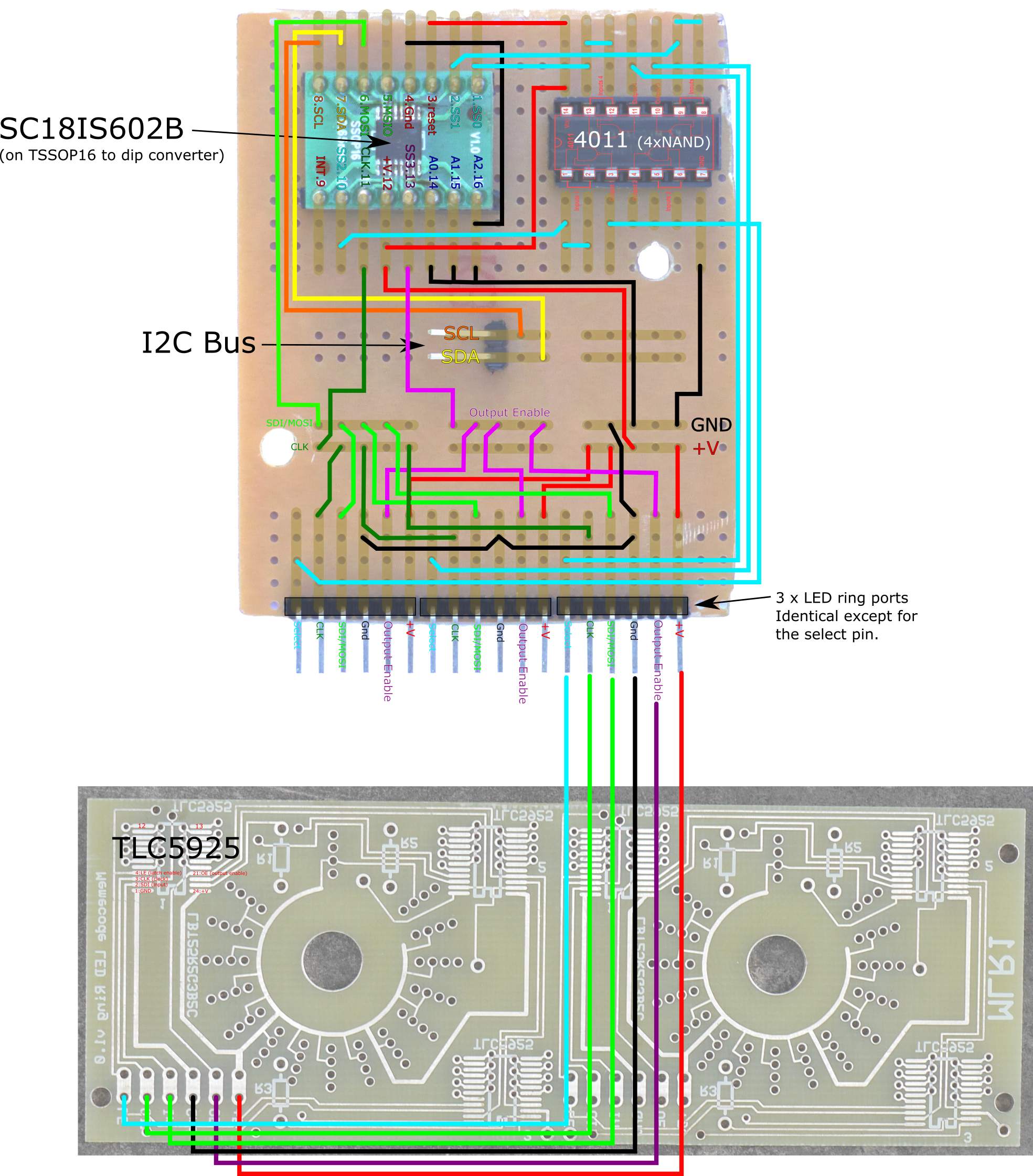
This is the circuit:

The code I'm using to setup the bridge:
        uint8 MsbOrder = 0, Mode = 2, SpiClockRate = 1;
        WriteI2C(SC18IS602B_ADDR,
                 0xf0,
                 (uint8)
                 (
                    (MsbOrder << 5) |
                    (Mode << 2) |
                    (SpiClockRate)
                ));

        // Enable GPIO on SS3
        WriteI2C(SC18IS602B_ADDR,
                 0xf6, // GPIO enable
        #if DEBUG_USE_GPIO
                 (uint8) 0x0F); // All SS pins GPIO
        #else
                 (uint8) 0x08); // SS3 is GPIO (output enable)
        #endif

        // Set mode on SS3
        WriteI2C(SC18IS602B_ADDR,
                 0xf7, // GPIO config
        #if DEBUG_USE_GPIO
                 (uint8) ((1 << 6) | (1 << 4) | (1 << 2) | (1)) ); // Push pull mode for all SS pins
        #else
                 (uint8) (1 << 6) ); // Push pull mode for SS3
        #endif
I tried setting the select lines to GPIO and just driving them high as I needed. That code is selected by defining DEBUG_USE_GPIO to 1. However when I try that no SPI data is transmitted into the LED driver chips.
I'm using the last select line as GPIO to turn off the LEDs until I have finished updating all the data strings.
The code to actually transmit the data is:
    typedef char LedRingBits[6];
    LedRingBits r[2];

    ZeroObj(r);

    #if DEBUG_USE_GPIO
    // Turn off output enable, turn on select line
    WriteI2C(SC18IS602B_ADDR,
            0xf4, // GPIO write
            (uint8) (LED_OUTPUT_DISABLE | Channel) );
    #else
    EnableLedRing(false);
    #endif

    #define SetLedBit(out, in, comp) \
        if (Col##in.comp()) \
        { \
            int Bit0 = LedRingAddr[Led##in].comp; \
            r[out][(Bit0>>3)] |= 1 << (Bit0&0x7); \
        }

    if (Led0 >= 0 && Led0 < 16)
    {
        SetLedBit(1, 0, r);
        SetLedBit(1, 0, g);
        SetLedBit(1, 0, b);
    }

    if (Led1 >= 0 && Led1 < 16)
    {
        SetLedBit(0, 1, r);
        SetLedBit(0, 1, g);
        SetLedBit(0, 1, b);
    }

    if (WriteI2C(SC18IS602B_ADDR,
                 Channel,
                 (uint8*) &r[0], sizeof(r)))
    {
        // This forces the SPI transfer to complete before we do anything else
        ClearIntLedRing();
    }

    #if DEBUG_USE_GPIO
    // Turn on output enable, turn off select line
    WriteI2C(SC18IS602B_ADDR,
            0xf4, // GPIO write
            (uint8) 0);
    #else
    EnableLedRing(true);
    #endif
Where 'channel' is 0x1, 0x2 or 0x4. Basically the bit that should drive just one slave select line high (not all).
I don't even know if I can say it's hardware or software at this point. I've triple checked for shorts or misplaced lines in the hardware. Voltages seem good (except for the slave select lines themselves).
I'm not sure if I need a decoupling cap on the power rails of this chip. Could that be a problem?
The bar/reset line is just attached to +V… which I assume is ok? (Active low according to the spec).
I've swapped the SC18IS602B chip out for another one, and got the same results. (Just in case the chip had gone bad).
Edit:
Here is v2 of the breadboard:
This is working better. The main difference is that the slave select lines are inverted with a 4011 NAND IC. Also there is now a 100nF cap between the GND and +V pins of the bridge chip. The result is that SPI output #1 is now independent of #2… but changing #2 affects #1. So half way there.
Edit2:
The final issue where changing LED ring #2 also affected LED ring #1 was traced back to an intermittent short on LED board #1 that only occurs when the PCB board is slightly flexed, as it is in the chassis (the screws are on the very edges pulling the PCB towards the chassis, and the LEDs in the middle act to prevent that). This would pull the latch enable line (LE) high all the time, resulting in that board always responding to SPI data, even when intended for another LED ring board. OMG it works!
Best Answer
Fret, those parts are working exactly as they should - but they aren't really compatible with regards to chip-enable.
As is standard with both I2C and SPI, the chip-enables on the SC18IS602B are all low-true. They would all be high when idle, and only one (the selected one) should be low when transferring data.
The TLC5925, on the other hand, has a latch that is transparent when LE is high, and latched when low. It's the opposite polarity from the chip-enables. That's why you are seeing what you are seeing.
What you need is an inverter between each chip-enable and its respective LE.