I want to switch a 12 V pump from the digital output of an arduino. I have tried using 5 V relays by using this schematic:
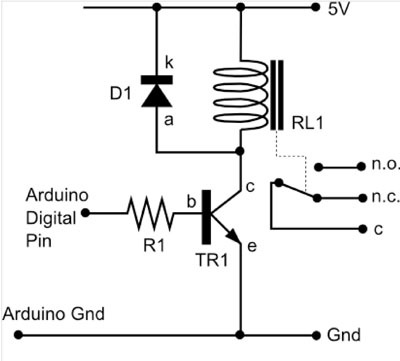
and put two of these in parallel. The power they are getting is from the arduino itself which is connected by 12 V in V-in. The relays behave abnormally. Can I get an arduino to switch on a 12 V pump and a 24 V pump?
Best Answer
What you show is a good topology. However, there are details in parts values that matter.
One problem may be that the relays require too much current from the 5 V supply. You say you have 12 V available, from which the 5 V is derived anyway. A better solution is to power the relays from 12 V. Very likely the same relay series you are using has a version with a 12 V coil. That is a very common coil voltage.
Relays in a series have about the same coil power. The 12 V version will need about 5/12 of the current the 5 V version does. For example, if the 5 V version requires 60 mA, then 12 V version will require about 25 mA.
Running the relays from 12 V does some good things:
This can be a significant issue if the 5 V is being linearly regulated from the 12 V. A extra 100 mA, for example, from the 5 V supply cause additional 700 mW dissipation in the regulator. That might be the difference between OK and too hot.
The other issue is that you have to make sure the transistor is driven properly. That means it needs enough base current to be saturated when on.
Let's say the 12 V relay takes 25 mA, just to pick something as example. Let's say the transistor can be counted on to have a gain of at least 50. That means the base current needs to be (25 mA)/50 = 500 µA minimum. Figure the B-E drop is 700 mV, so that leaves 4.3 V across the base resistor. (4.3 V)/(500 µA) = 8.6 kΩ. That allows for the absolute minimum base current. To get solidly into saturation, I'd double the base current, which means half the resistance, or 4.3 kΩ. Any handy value from about 2 kΩ to 4.3 kΩ would be fine.