I'm guessing it's a Faraday cage around the receiver, but don't know why they might need one. Is there some sort of common interference around 38kHz (their operating frequency)?
It's the only component I think I've used that gets this special treatment. A larger cage may be around one in a VCR,
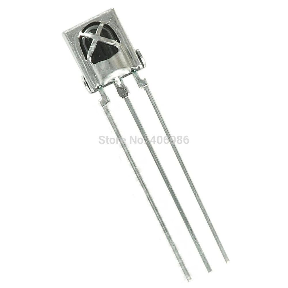
and a little baby cage sometimes appears around the standalone PC mount component:
Thanks for your insight!
Best Answer
[ added 2_D resistor_grid methodology for exploring shielding topologies ]
You want that IR receiver to respond to photons, not to external electric fields. Yet the photodiode is a fine target for trash from fluorescent lights (200 volts in 10 microseconds) as the 4' tube has that restrike-the-arc action 120 times a second. [or 80,000 Hertz for some tubes]
Using the parallel-plate model of capacitance, $$C = E0*Er*Area/Distance$$ with diode area of 3mm*3mm and distance of 1 meter, the capacitance is $$9e-12Farad/meter * (ER=1 air) * 0.003*0.003/1$$ or ~~ 1e-11 * 1e-5 = 10^-16Farad
What current from a fluorescent light, at 20Million volts/second slewrate? $$I = C * dV/dT$$ or I = 1e-16Farad * 2e+7 Volt/second = 2nanoAmp
That ---- 2 nanoAmp ---- apparently is a big deal (the edge rate, 10 us, is close to 1/2 period of 38 kHz).
The metal cage protects by attenuating the Efield in an exponentially improving manner; thus the further the cage is in front of the photodiode, the more dramatic the Efield attenuation. Richard Feynman discusses this, in his 3-volume paperback on physics [I'll find a link, or at least a page #], in his lecture on Faraday cages and why the holes are acceptable IF the vulnerable circuits are spaced back several hole-diameters. [again, exponential improvement]
Are other Efield trash sources near? How about digitally noisy logic0 and logic1 for LED displays; 0.5 volts in 5 nanoseconds, or 10^8 volts/second(standard bouncing of "quiet" logic levels, as MCU program activity continues). How about a switching regulator, inside the TV; regulating off the ACrail, with 200 volts in 200 nanoseconds, or 1Billion volts/second, at 100 kHz rate.
At 1 billion volts/second, we have 100 nanoAmps aggressor currents. Of course, there should be no line-of-sight between a switchreg and the IR receiver, is there?
Line-of-sight does not matter. The Efields explore all possible paths, including up-and-back-down or around-corners.
simulate this circuit – Schematic created using CircuitLab
HINT TO BEHAVIOR: the Efields explore all possible paths.
================================================
From the master of clear-thinking himself, in his own words, I offer the explanation of Mr "Why did the space shuttle explode high over Cape Canaveral?", the gleeful Dr. Richard Feynman.
He provided a 2 year introduction to physics at Caltech, approximately 1962. His lectures were transcribed, very carefully to serve as reference material, [its worth getting these 3, and re-reading them every 5 years; also, the curious teenager will savor the realworld discussions in Feynman's style] and published in 3 paperback volumes as "The Feynman Lectures on Physics". From Volume II, focused on "mainly electromagnetism and matter", we turn to Chapter 7 "The Electric Field in Various Circumstances: Continued", and on page 7-10 and 7-11, he presents "The Electrostatic Field of a Grid".
Feynman describes a infinite grid of infinitely long wires, with wire-wire spacing of 'a'. He starts with equations [introduced in Volume 1, Chapt 50 Harmonics] that will approximate the field, with more and more terms optionally usable to achieve greater and greater accuracy. The variable 'n' tells us the order of the term. We can start with "n = 1".
Here is the summary equation, where 'a' is the spacing between grid wires:
$$Fn = An * e^-Z/Zo$$ where Zo is $$Zo = a/(2*pi*n)$$
At distance Z = a above the grid, thus we are 3mm above a grid spaced 3mm, and using only the "n = 1" part of the solution, we have $$Fn = An * e^-(2 * pi * 1 * 3mm)/3mm$$
Since this Fn is e^-6.28 smaller than An, we have rapid attenuation of the external electric field.
With 2.718^2.3 = 10, 2.718^4.6 = 100, 2.718^6.9 = 1000, then e^-6.28 is about 1/500. ( 1/533, from a calculator)
Our external field of An has been reduced by 1/500, to 0.2% or 54dB weaker, 3mm inside a grid spaced at 3mm. How does Feynman summarize his thinking?
"The method we have just developed can be used to explain why electrostatic shielding by means of a screen is often just as good as with a solid metal sheet. Except within a distance from the screen a few times the spacing of the screen wires, the fields inside a closed screen are zero. We see why copper screen---lighter and cheaper than copper sheet---is often used to shield sensitive electrical equipment from external disturbing fields." (end quote)
Should you seek a 24 bit embedded system, you need 24*6 = 144dB attenuation; at 54dB per unit_spacing, you need to be 3*wire-wire spacing, behind the grid. For a 32 bit system, that becomes 32*6 = 192 dB, or nearly 4*wire-wire spacing, behind the grid.
Caveat: this is electrostatics. Fast Efields cause transient currents in the grid wires. Your mileage will vary.
Notice we only used the "a = 1" part of the solution; can we ignore the additional parts of the harmonic/series solution? Yes. With "n = 2", we get the attenuation * attenuation, and "n = 3" yields atten * atten * atten.
=================================================
EDIT To model more common mechanical structures, to determine the ultimate trash levels as an Efield couples into a circuit, we need to know (1) the impedance of the circuit at the aggressor frequency, and (2) the coupling from a 3_D trash aggressor to a 3_D signal chain node. For simplicity, we'll model this in 2_D, using the available grid_of_resistors
simulate this circuit