I've got an ordinary PC motherboard. So, out of curiosity, I started looking at the power circuits on it and found several large 1000–1500 μF electrolytic caps:
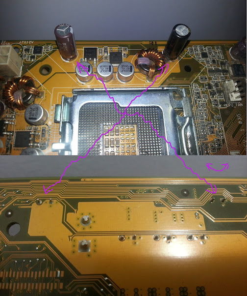
It's easy to see that their cathodes are not connected to any wires on the back side of the board. However, they aren't connected on the front side as well:

At first I thought that these might be soldered in as reserved components, uhhm… but now I'm inclined to reject that hypothesis. It makes little sense; and what's convincing the most is that other similar caps are wired in the same anode-only fashion.
I guess that this might work, because of electrostatic induction happening inside the caps, which would still allow to store energy in there over 1 wire only (and thereby absorb unwanted ripple current) – but wouldn't that effectively reduce the caps' capacitance?
Also, can the cathodes be wired back to ground, theoretically? Will this enhance power regulation stability?
Finally, I have a suspect that this could be related to the obvious difficulty of routing the ground wire to nearly every component on the board. If I'm correct, is connecting of EL caps by 1 wire only a common practice in the industry? Or did I just notice an extremely dirty awful hack, which I shouldn't ever repeat in my designs?
Best Answer
PC motherboards have more than just the top and bottom copper layers that you can see. The capacitors are connecting to a hidden layer somewhere in the middle. In cross section, it looks like the example labled "1" in this picture:
(image courtesy Wikipedia)