I'm a software engineer diving head-first into the world of embedded systems design and development. This question is basically about "plumbing" — what's the best way to physically wire up a particular circuit. So:
I have a small microcontroller evaluation module, the CC11EMK, with a 2×5 header debug port.
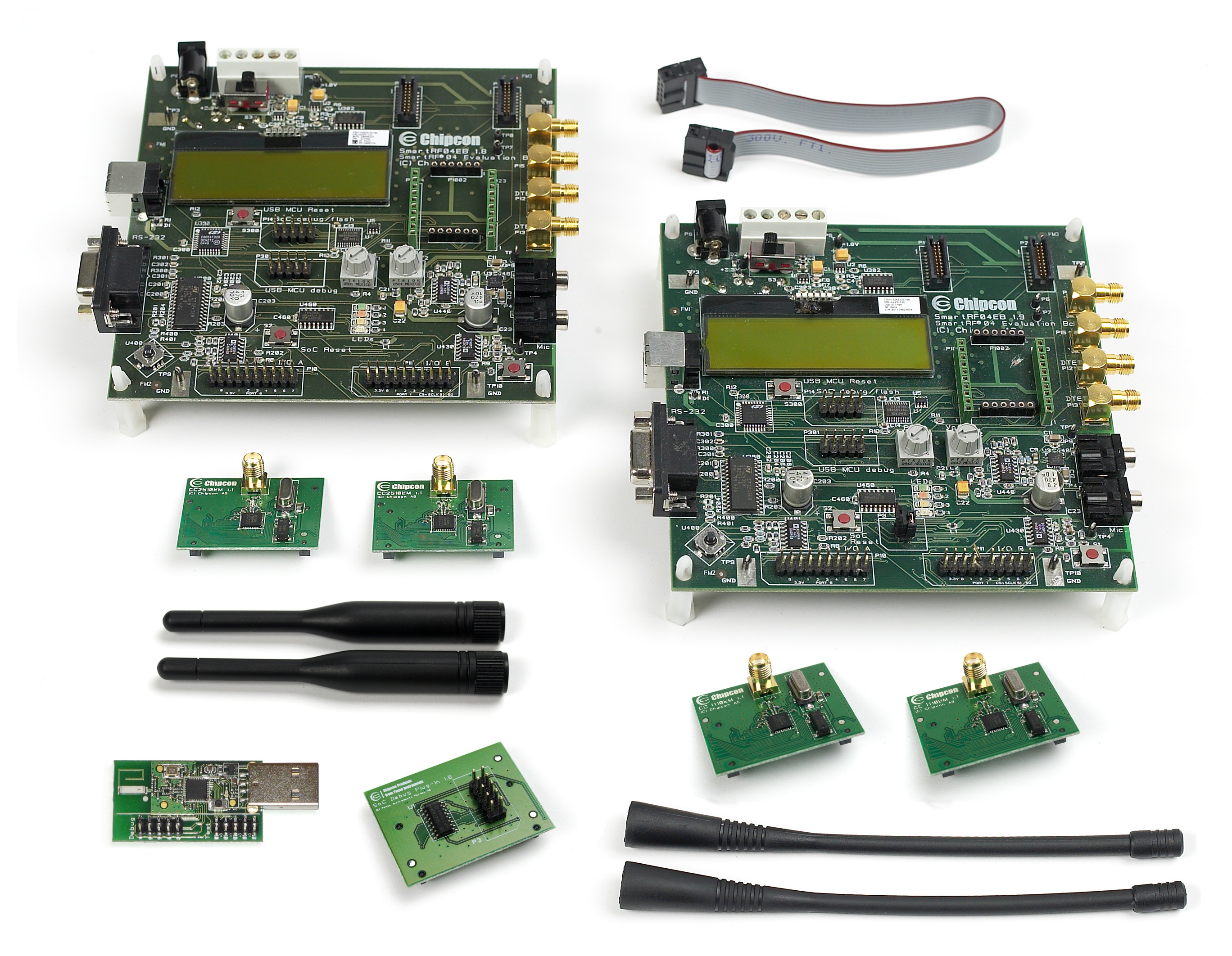
I also have an evaluation board (the CC1110-CC1111DK) to program the evaluation module, also with a 2×5 header. (The dongle is in the lower left) below:
The two are connected with a 10-wire ribbon cable.
My problem is that the microcontroller reset pin is sensitive to noise, causing random resets. Not fun. The datasheet for the CC111 has this to say in section 6.11.1:
The RESET_N pin is sensitive to noise and can cause unintended reset of the chip. For a long reset line add an external RC filter with values 1 nF and 2.7 kOhm close to the RESET_N pin.
I also have some sensors and an SPI bus setup on a breadboard.
What's a relatively simple way to insert the resister and the capacitor into the circuit? I thought I might be able to stick a pair of 2×5 headers onto the breadboard, use two ribbon cables, and wire corresponding pins together with the exception of the reset line, which I'd pass through the RC filter. But I don't think that can work on a breadboard — the header won't fit over the gutter, so no matter how I do it, I'd be shorting together pairs of pins.
Any suggestions?
Best Answer
Putting a resistor in line as you describe is one way of dealing with the noise problem, but it also requires hacking up the board. I'd try simpler solutions first that only require adding components, not breaking things. You can always break a trace later if the simpler solutions don't work, but I think there is a good chance they will do just fine.
You don't say what microcontroller, but from the description it seems it has a typcial reset input with negative logic. Hold it low, and the micro stays in reset. Hold it high and the micro is allowed to run. Actually I'd rather call that a RUN input so that the name corresponds to positive logic, but that's just silly me trying to avoid confusion.
In any case, whatever micro this is is apparently OK with 1 nF on this line. Go ahead and put that there. That alone might be enough to solve the problem. The noise is probably capacitively coupled so is coming in with only a few 10s of pF at most in series. 1 nF should swamp that. I would also add a pullup to Vdd. That makes it so the noise has to provide more current to drag the line low, something it will have a hard time doing with the aformentioned capacitance in series. Again we don't know the micro or any of its particulars, or probably more importantly the particulars of the programming jig, so I'd stick with 10 kΩ as a pullup.
So to summarize: Slap 1 nF to ground on the RUN line and 10 kΩ to Vdd and leave the surgury for mad scientist stuff you'll be adding later. Most likely that will fix things well enough.