I am quite new to electronics but I'm planning to build a device for routing analog audio inputs (cinch) to one output. I want to select one input channel (using a raspberry pi) to forward to the output channel.
After a lot of reading about the basics, I found an analog multiplexer (the DG409) that seems to be able to solve this.
My question is, can I just solder the left and right cinch channels to the S1a and S1b (and so on) and wire the grounds together or is there anything else I need to do?
Edit:
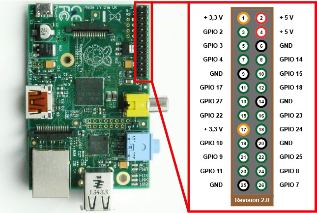
As @pjc50 pointed out, I also need to supply suitable V+ and V- for the device. Looking at the available pins of the raspberry pi, I can find a suitable +5V supply but no -V. The data sheet of the DG409 say that it can be operated in either single or dual supply. To run it with single supply, do I have to connect V- to the GND or leave it unconnected?
And @nick-johnson commented that my signal needs to stay between the positive and negative rails. My signals all come from line-out jacks and should have only minimal current according to wikipedia:
Line outputs are intended to drive a load impedance of 10,000 ohms; with only a few volts, this requires only minimal current.
So that shouldn't be a problem, right?
Best Answer
Modern mixed signal ICs (audio processors and such - not op-amps and high end devices) mostly use a single rail power and their analog output is already centered around some DC voltage and does not go below zero, so with those kind of chips you can use the analog multiplexer as is.
But if you have a line out which is either floating or centered around zero volts, or can be something that you don't really know what it is (such as an external connector), then you must use a coupling (DC blocking) capacitor at the line out pin, and then use a "biasing" resistor to weakly pull the zero point to a suitable DC voltage between the rails. If your positive rail and ground are clean, then you can use a small resistor (something like 10K ohm) to both VCC and GND from the "other" end of the capacitor. Then you have an audio signal that sits nicely between the rails.
If the vcc (or avdd) signal is not clean enough, you must use a separate clean power source (a reference diode or good ldo) at a suitable voltage level to bias the signal to. For example, LDO output of 1.5 volts, and a 10K resistor from the signal to the LDO voltage.
At the other end you must use a similar blocking capacitor and just to be sure, weakly (100K) pull the other end to the common (ground) of the receiving line in. Depending on what the input impedance of the line in is (in the stone age it used to be 600 ohms but now it's rare to find such low impedance line in), you must determine the size of the coupling capacitor - it must be large enough that the bass frequencies don't cut off too much - because the coupling capacitor forms an RC filter together with the input impedance. 10 microfarades should be in the ball park.