Question on use of clock in SDC style IO delay constraints
The intention of this write up is to cast some clarity on how an FPGA IO interface has to be constrained. As a preamble the two timing constraints which can be used for constraining an FPGA IO interface are:
-
set_input_delay
Usage: set_input_delay [-add_delay] -clock [-clock_fall] [-fall] [-max] [-min] [-
reference_pin ] [-rise] [-source_latency_included] -
set_output_delay
Usage: set_output_delay [-add_delay] -clock [-clock_fall] [-fall] [-max] [-min] [-
reference_pin ] [-rise] [-source_latency_included]
The set_input_delay constraint makes sure that an input to the FPGA from an external chip meets the internal setup and hold requirements. Similarly the set_output_delay makes sure that the data driven from an FPGA meets the setup and hold requirements of the external chip. The constraints use various timings like [tCO tSU tH] of the external chip, PCB trace delay, clock skew etc for the estimation. These stuff are pretty clear to me except the "use of clock". Here starts the confusion!
Both the constraints specify the delay values with respect to a clock. Now comes the concept of a virtual clock, a clock which feeds the external chip and not existent inside the FPGA. I have seen Intel FPGA(previously Altera) documentations prescribing the use of a Virtual Clock for constraining all IO interfaces. But it did not make complete sense to me till now!
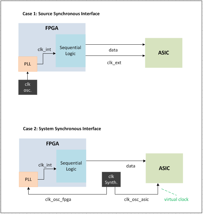
Regarding the clocking, there are two cases I'm interested in. Please check the attachement for the drawings.
-
Case 1: If I have source synchronous interface like an SDRAM or QSPI interface the FPGA internally generates the clock for the external chip. In the figure clk_ext and data are sent from the FPGA. So should the SDC constrainting use a virtual clock or a generated clock from FPGA?
-
Case 2: There is an external clock synthesizer feeding the FPGA and the ASIC clocks. The clocks clk_osc_fpga and clk_osc_asic may or maynot be related as far as we are concerned. But there is indeed a data flow from the FPGA -> ASIC. Note that the data generation inside FPGA is done using clk_int which is not sent out! So is this where we should use a virtual clock? And how would the timing analyzer model the skews or frequency differences in the virtual clock with respect to the internal fpga clock?
I would appreciate any advice on this. And thanks for reading a really long question.
Update on the Question:
In one of the designs, I was able to estimate the latency of the clk_int with respect to the clk_osc_fpga. I found it to be around -1.3ns. So basically this means that the virtual clock or clk_osc_asic is propagated advance with respect to fpga internal clock clk_int.
The question is how do I constrain this latency? Should I use the set_clock_latency on the virtual clock? Or just adjust the phase of the virtual clock when using create_clock constraint? Also how to specify the sampling edge of the virtual clock?
Thanks again for the support.
Best Answer
Consider the above case, where block is sitting outside FPGA and FPGA is feeding synchronous data to it via an output port. Here, the timing analyser won't be able to analyse the path Reg A --> a --> b --> Reg B. Because the clock freq. and the latency in the physical path outside FPGA is unknown to the tool. So we will define an output delay at the output port with respect to an imaginary clock clock_in_virtual called virtual clock. The output delay will constitute the route delay, delay of b and the setup time of Reg B (Delay of a, and clock-q delay of Reg A are already known to the timing analyser tool). We can model the time period and latency of the virtual clock. The tool can now analyse this path for setup-hold violations. Suppose we don't use virtual clock and we define output delay with respect to clock_in itself, such an analysis will be pessimistic for setup and optimistic for hold, because the capture clock latency is taken as zero. The same idea is used in input ports too. I hope this makes some sense to you now on why virtual clocks are used.
Case I:
Here the design is source synchronous. Data out and clock out will change in known timing and the physical path is irrelevant because the route delays for both clock and data lines would almost be equal. This ensures best timing for setup and hold. Hence you can constraint output delay with respect to the generated clock to constraint the path. Virtual clock is not needed.
Case II:
To analyse this, both the clocks should be synchronous. You have to define a virtual clock that model the characteristics and relationship between ASIC clock and FPGA clock. The output delay is then constrained with respect to the virtual clock. The latency of the virtual clock is defined as the insertion delay/network latency of the clk_int.