If your output voltages are fixed you should be able to design it with linear regulators with a minimum of voltage drop over the regulators. And 1A is not the end of the world.
A switcher would be more appropriate if you have a variable output voltage. A linear regulator which can supply 30V @ 5A, but which is set to 1V out it will have to dissipate 150W.
An SMPS is dimensioned for a certain input voltage, output voltage and current. If you would vary the output voltage its efficiency will be lower. You won't get the 90% figure manufacturers boast about over you full range, maybe more like 75 to 80%.
edit
If you want the +/-15V adjustable I'd go for the SMPS, for the dissipation reason I mentioned. You can attack the ripple with a pi-filter. A high frequency switcher (like 1.5MHz) will allow for a smaller coil.
Your solution started out as bearable (5V at 100mA) but ended up completely unacceptable at 500 mA. You say that your "wall wart" is rated at 300 mA. When you supply a voltage using a linear regulator the current in is the same as the current out - the regulator drops the difference in voltage. So here if you draw 500 mA at 5V you must supply 500 mA at 12V or 24V. The transformer will be overloaded in either case.
If the ratings are as you say then a potentially acceptable solution is to use a switching regulator (SR) operating from 24V in. \$5V \times 500 mA = 2.5 W\$.
\$24V \times 5 W =~ 210 mA\$. If the SR is 80% efficient (easily achieved) that rises to 260 mA. As that is liable to be an occasional requirement the total current at 24V will probably be acceptable with a 300 mA supply - depending on how many solenoids you wish to maintain on.
If you switch only one solenoid on at once the current drain with N activated is \$20 \times N + 20 mA\$. The surge current is essentially immaterial.
If you wanted more than 3 or 4 solenoids then current drain at 5V may need to be limited.
e.g.
- 10 solenoids at 20 mA = \$200 mA\$
- Balance = \$300mA-200mA = 100 mA\$
- Available current at 5V at 80 % efficient = \$ 100 mA \times \frac{24}{5} \times 0.8 = 384 mA\$, say \$400 mA\$.
Note that when a switching regulator is used, using a higher input voltage will result in less input current drain. Hence it is better here to use the full 24V supply.
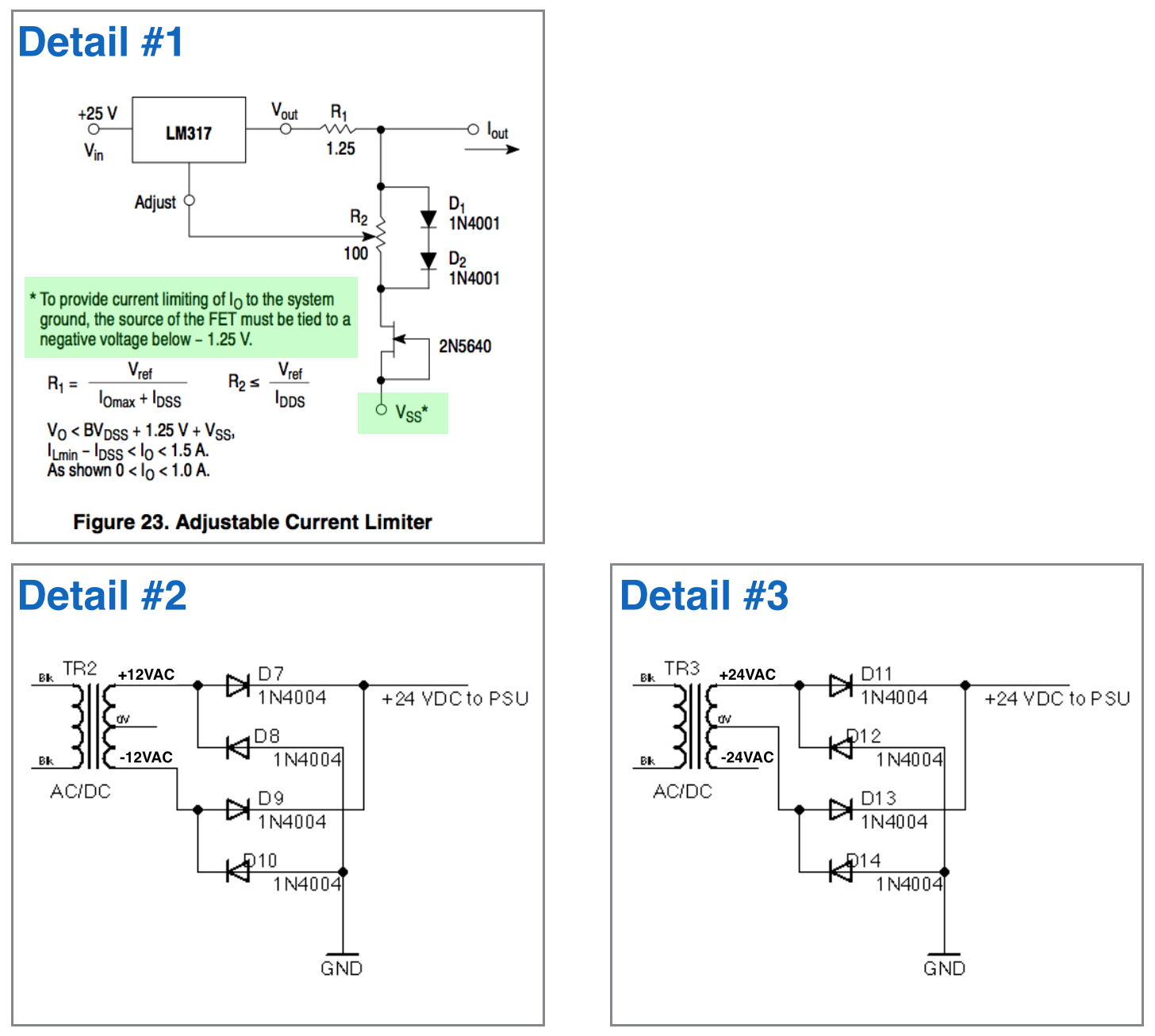
Note also that if the transformer is a genuine 24 VAC then the rectified DC will be about \$24 VAC \times 1.414 - 1.5V - \$ "a bit" \$~= 30 VDC \$
Because:
\$VDC_{peak} = VAC_{RMS} \times \sqrt{2} ~= VAC \times 1.414 ~= 34 V\$.
A full bridge rectifier will drop about 1.5V.
34 VDC is peak voltage and available DC will be slightly lower - depends on load. There will be "a bit" of ripple and wiring loss and transformer droop and ...
At 80% efficiency this gives a 24VAC to 5V DC current boost of \$ \frac{30}{5} \times 0.8 = 4.8:1 \$
e.g.
- for 48 mA at 5V you need 10 mA at 30V.
- for 480 mA at 5V you need 100 mA at 30V.
So you about get 10 solenoids plus almost 500 mA at 5V DC :-)
One solution of many:
There are many SR IC's and designs. Here a simple buck regulator will suffice.
You can buy commercial units or "roll your own". There are many modern ICs but if cost is at a premium you could look at ye olde MC34063. About the cheapest switching regulator IC available and able to handle essentially any topology. It would handle this task with no external semiconductors and a minimum of other components.
MC34063. $US0.62 from Digikey in 1's. I pay about 10 cents each in 10,000 qauntity in China (about half Digikey's price).
Figure 8 in the datasheet referenced below happens to be a "perfect match" to your requirement. Here 25 VDC in, 5V at 500 mA out. 83% efficient.
3 x R, 3 x C, diode, inductor. It would work without alteration at 30 VDC in.
Datasheet - http://focus.ti.com/lit/ds/symlink/mc33063a.pdf
Prices - http://search.digikey.com/scripts/DkSearch/dksus.dll?Detail&name=296-17766-5-ND
Figure 8 in the LM34063 datasheet shows ALL component values except for the inductor design (inductance only is given). We can spec the inductor for you from Digikey (see below) or wherever and/or help you design it. Basically it's a 200 uH inducor designed for general power switching use with a saturation current of say 750 mA or more. Things like resonant frequency, resistance etc matter BUT are liable to be fine in any part that meets the basic spec. OR you can wind your own for very little on eg a Micrometals core. Design software on their site.
From Digikey $US0.62/1. In stock. Bourns (ie good).
Price:
http://search.digikey.com/scripts/DkSearch/dksus.dll?Detail&name=SDR1005-221KLCT-ND
Datasheet:
http://www.bourns.com/data/global/pdfs/SDR1005.pdf
Slightly better spec
Best Answer
A 24VAC transformer will give you as much as 40VDC with a light load. That's pretty marginal for an LM317 with zero output. Way too close for comfort, in my opinion.
Anyway, if you were to use a third LM317 to regulate the input voltage down to +5VDC, you could use that 5V to power a 7660 charge pump to generate about -4.5V for your JFET current sink.
The filtered unregulated voltage likely is too close to the maximum 40V input voltage of the 317 (actually maximum difference between in and out). Maybe you can use 317HV, but an 18V transformer would be better.
Unfortunately the LM7805 is only good for 35V max input, so you'd need a Zener in series with the input of the LM7805 if you wanted to use that part to drop the voltage for the 7660 with a 24VAC transformer.