I have two things to say before I ask my question:
- I am a layman with very little theoretical understanding of electronics (my question text will prove this, trust me). Sorry if my idea of the problem is a weird mess.
- Coming from StackOverflow, I know that asking a question about such a specific scenario/problem may not add much value for others. I really just need help understanding what's going on here and I hope there is some general understanding in the end that might also help others.
What I want to achieve
I want to build a little box, exposing three rotary dials (or potentiometers in my case), each controlling the brightness of one channel of a single RGB-LED (common ground).
What I have tried
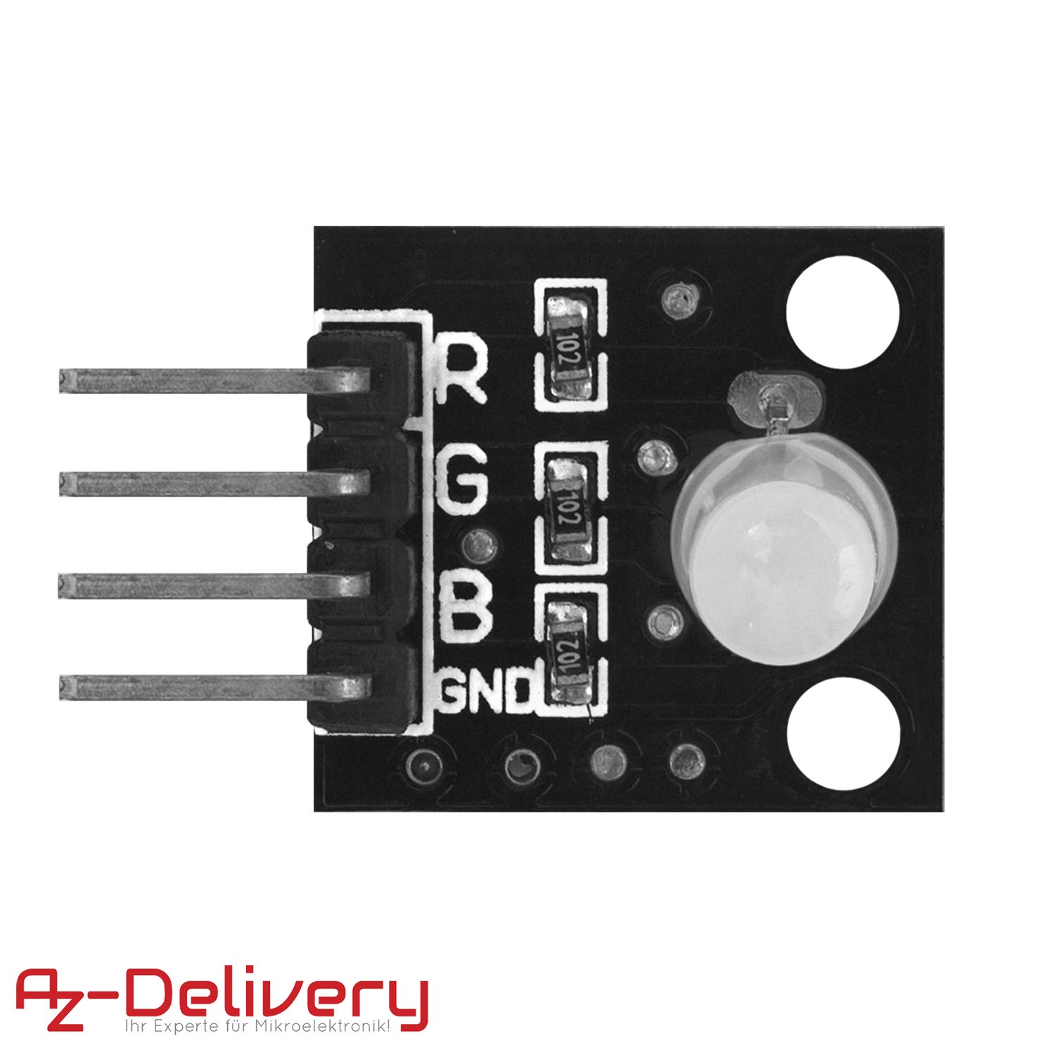
I bought three simple PWM-Modules (link to the product page for reference, not a referrer link!), each providing a potentiometer and +/- connections for the DC in and "motor" out (they're primarily meant for motors). I don't have the schematics of those, so my sketch below shows an abstraction of the modules. I also bought a little RGB-LED module that's nothing more than the LED and three resistors (pretty superfluous).
Here is a plan of how I prototyped my build:

The problem
For me (as an absolute layman) this looks like it should work. But the problem is that as soon as I turn up one of the PWM pots to control a single LED (of the RGB LED package), all three LEDs light up (nice and slow, so at least that works).
When I disconnect two of the LEDs, only one works (obviously). When I measure the voltage on the disconnected "out +" (from PWM out + to the LED) – all three get the same voltage. How is this possible? I want to control the RGB colors independently.
Is it possible that the PWM modules are not made to work in such a parallel configuration? How can I solve this? Thank you in advance!
PS: I know so little I don't even know how to correctly tag this question 🙁
Best Answer
Your LED array is common-cathode so you cannot use it with these PWM modules. This is inherent to the LED device itself and cannot be changed.
The PWM modules have the + in and + out more-or-less connected together (there's a polyfuse in each line) and that won't work for you.
You can use individual LEDs with resistors. It's also possible to use a common-anode RGB LED + resistors however the fuses will be paralleled, which is not ideal.
The module schematic (simplified) looks like this:
simulate this circuit – Schematic created using CircuitLab
LED array:
simulate this circuit