I'm looking for a brand of Toroid isolation transformer with electrostatic shielding. There may be one brand which has this. Unless there is just none in the whole world? Is it not possible to put electrostatic shielding in any Toroid isolation transformer?
Original message (findings: It's a semi isolation transformer)
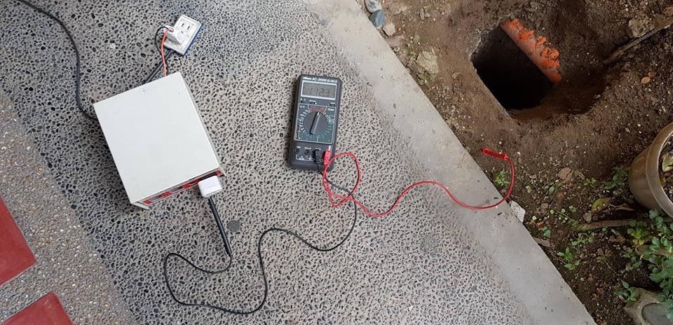
I bought a Hammond Isolation Transformer (dual 234v/117v primary and secondary) for isolating test projects from ground. But when I measured it from one of the output to the soil, it measures 112.3 volts. The other lead is near zero. I thought it was supposed to be isolated to ground.
Here's the model.
https://www.hammfg.com/electronics/transformers/power/1182.pdf
I chose the m117 model or 500va.
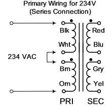
Here's the primary connection
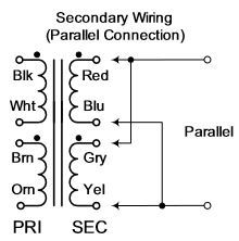
Here's the secondary connection
Note all the 4 windings have no connection to each other initially (tested using continuity meter). Even after connecting them right. There is still no connection between primary and secondary (any of the wires), when not powered.
It's not an autotransformer which has connection between one of the leads of the primary and secondary. Unless a toroid autotransformer has no connections between the primary and secondary too?
So why does one of the leads reads 112.3 volts to the soil? Isn't it an isolation transformer? But the primary and secondary windings are supposed to be separate which is what makes isolation transformer, isn't it. What do you think?
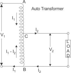
An autotransformer only has one winding. The Hammond 1182 toroid has 4 windings. So how could it still be an autotransformer??
Best Answer
First, the 1182 series are not truly "isolation transformers". At least not on the linked datasheet. They are regular transformers with electrically unconnected secondary winding. While the secondary winding is not connected, the area of windings overlap is huge along the toroidal core, and thus there is capacitive coupling, since the whole thing operates on AC.
My take on the difference in readings is that by design, the windings are made in multiple layers, so one end is closer to primary winding, and the capacitive coupling is higher, while the other end is likely on the surface of the transformer, and has higher distance from primary winging.
The value of capacitive coupling could be 1 nF - 2 nF, which is about 3 MOhms, so a high-impedance DMM will see some AC voltage between floating leads and earth ground. And the effective leakage will be about 30 uA, which will be easily grounded once you connect it to your workbench ground.
True "line isolation transformers" usually include a single-layer winding (for toroidal core, and a non-shorted copper foil in rectangular bobbins, as Jeroen3 commented) with only one end exposed, which is connected to enclosure ground. In this case the cross-talk between primary coil and secondary coils is minimized, see Section "Line Transformers"
from main Hammond transformer catalog.