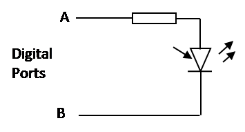
I am trying to light up some LEDs on my Rustler VXL RC car only when braking/reversing.
I found out that on my receiver I have three wires: black(-), red(+), white(+). The one that interests me is the white (signal wire). This wire tells the speed controller to either turn the motor clockwise or anticlockwise.
White wire voltage is as follows.
– no throttle: 0.55V
– full throttle forward: 0.71V
– full throttle reverse: 0.39V
So, when I brake/reverse the voltage drops from 0.55V to some value but no less than 0.39V.
How can I design a system to catch that voltage drop and activate a switch to light up the LED?
What parts would I need to buy?
And, what's the difficulty level for this?
Thanks

Best Answer
It's probably not that simple. How did you measure the voltage level, with a multimeter I expect? It is probably a pulse stream with the information actually encoded in the length of the duration of the positive pulses. Probably the pulse varies from 1 to 2 ms. This looks like a voltage signal only because the meter averaged it over time.
If all the above is correct, then to use this signal you have to decode the pulse width. There are various ways to do that with most microcontrollers. The micro measures the pulse width, decides whether that indicates reverse or not, and turns on a output accordingly.
A simpler way to do this is to let your existing decoder decode the signal and see what it decides. Ultimately it's going to control the motor. You could have a transistor turn on whenever a negative voltage is applied to the motor. Probably the controller is pulsing the motor between 0 and full supply voltage when going forwards and 0 and negative supply voltage when going backwards. The fraction of time it spends on the supply voltage versus zero is how hard it drives the motor. By detecting negative voltage accross the motor, you should be able to tell when the controller is trying to back up.