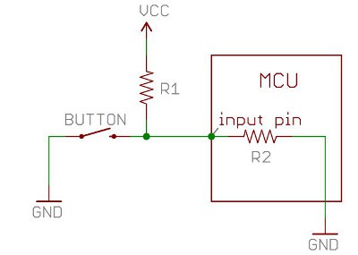
I understand that when the button is in its open state the voltage on the input pin should be fairly close to \$ V_{cc} \$ provided \$ R_1 << R_2 \$ as \$ V_{in} = V_{cc} \frac{R_2}{R_1 + R_2}\$. But, I do not understand why the voltage on the input pin changes to low (close to 0) when the button is closed.
Best Answer
When you press the button, you connect the input pin, and the bottom end of R1, to ground.
Current will flow through R1, and through the button to ground.