This will sound maybe stupid, but I'm amateur in electronics and I'm in process of learning.
I have previously analysed some basic circuits involving opamps, diodes etc.
Although some circuit looks simple (only few opamps, diodes, resistors, capacitors and sources), mathematics that describe that simple circuit can be very complicated, especially if we want to calculate full response of circuit (not steady state).
I was wondering, how then some complicated electronics schematics are analysed?
I mean there are devices containing hundreds of components inside it, it would be impossible to apply some circuit analysis methods there (KCL, KVL etc), right?
How important are those network analysing methods we are studying in school in practice (in repairing electrical devices)?
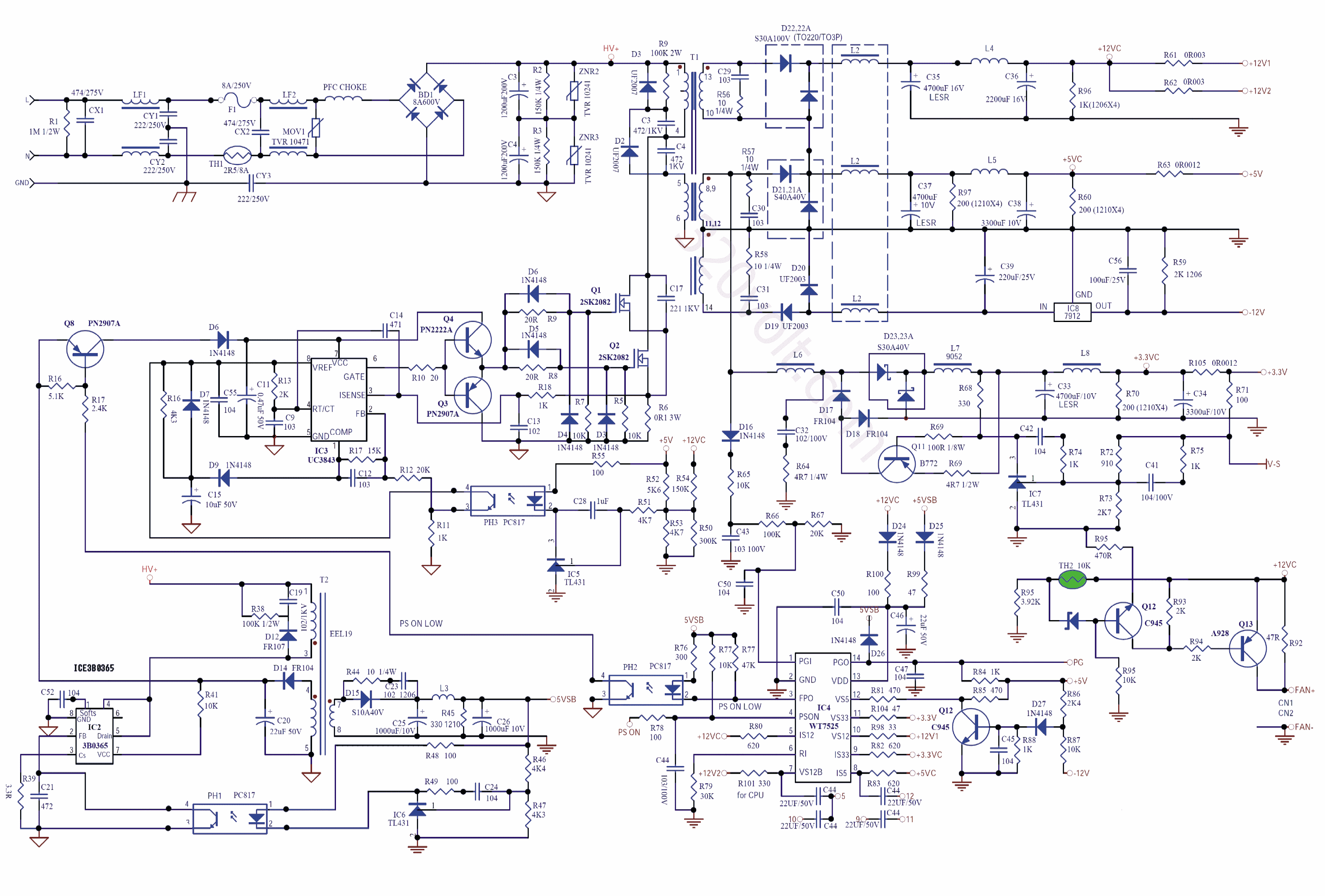
To clarify what I mean, lets look at one switched-mode power supply schematic I found on the web:

(source: 320volt.com)
Probably, professionals doesn't see there something terrific complicated, but to me, it is very complicated. If one has to repair this device for example, which knowledge he need to have? If he start measuring some voltages, or tracing signals waveforms on oscilloscope, he must need to know firstly what he should expect in normal circumstances (when device is working), so he can detect exact problem. But how can he know that if he doesn't analyse circuit mathematical, which would be quite impossible in this case, what returns us to first lines of my question 🙂
Best Answer
Basically for pen-and-paper analysis you break down the circuit in "logical" blocks, like in a block diagram and you mostly analyze them separately. I put that "logical" in quotes because it's not in any formal sense.
There are however fast SPICE simulators that can simulate an entire chip and these obey KCL, KVL etc. but may use somewhat simplified component models.
I should also note that breaking down circuits into simpler sub-components (as we do on paper) is also done in some software tools like HSIM. Hierarchical simulation is one of the tricks in the arsenal of fast SPICE simulators.
Regarding that SMPS schematic that was added as example: for pen-and-paper analysis you need to be familiar with the kind of circuit in question (starting with SMPS topology) and the identify the "macroblocks" like input filter, rectifier, main switcher[s], transformer, main controller IC (usually includes error amplifier), etc.