The answers already here describe the behavior you saw, but perhaps don't illuminate the "conventional" way of doing things.
The key behavior of a bipolar transistor (as opposed to FET) as wired here (common emitter) is that the transistor will attempt to draw an amount of current into the collector equal to Hfe (the transistor's current amplification factor, sometimes called beta) times the current into the base. Hfe is some more-or-less constant number in the range of 25 to 100 or more. With this behavior the transistor is useful for amplifying ("multiplying") analog signals, like audio.
However, we often want to just switch a current on or off, like for an LED. In that case, we want the transistor either off (conducting no current) or fully on (maximum current, given some series resistor, and the overall supply voltage) To arrange that state, we just have to apply a base current large enough that the transistor, in an effort to draw Hfe X Ib into the collector, would trying to set the collector voltage below the minimum possible, which is about Vemitter + 0.2 (so 0.2V in your example). When the transistor is in that state, it is said to be saturated.
A circuit is normally designed to employ each transistor in only one of these modes, either amplifying, or switching, with surrounding components selected to ensure that mode, and to focus on the particulars of that mode. So, in a circuit such as yours, a designer would make a rapid calculation of the LED (and thus collector) current required, divide by a low guess for transistor beta (say 40), arriving at the minimum needed base current, and arrange the base resistor to deliver that or more.
Exact base current is not important, but we do need to ensure that the transistor is saturated when on, because if it isn't, the collector will not sink to its lowest voltage, allowing a higher collector-emitter voltage. Though the current will be somewhat less, the voltage across the transistor will be substantially higher, requiring the transistor to dissipate much more heat (V x I) than necessary. That heat would either destroy a small transistor, or require a larger transistor or addition of a heat sink.
So, your first schematic is the sensible way to use the transistor for switching an LED. (Setting aside the waste of using a 24V supply requiring a large voltage drop somewhere.)
In the second schematic you stumbled upon use of the amplifier part of the transistor's range of operation. As noted, this is disadvantageous to the transistor heat wise if it actually worked. However, it won't work satisfactorily because, as others have mentioned, the Hfe value varies quite a bit from one transistor to the next, and also with heat. So you would not be able to set an accurate stable LED current that way anyway.
(To create an actual amplifier with a consistent and stable amplification factor, additional resistors and capacitor are needed to address the effect of Hfe variation.)
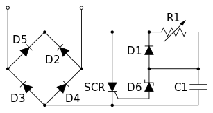
Wikipedia has some good examples about dimming. For as simple solution as possible (by electrical terms) I would use a transformer, full wave DC bridge and a thyristor. Again, wikipedia has a great picture of that
Note that thyristor dimmers usually make some radio frequency noise but as I see it, this is one of the simplest AC dimmers.
You will find more info about different dimmers on http://en.m.wikipedia.org/wiki/Light_dimmer
And although you would like to keep out from MCUs, at least think about them. If the thyristor-stuff goes over your head, try to use MCUs. You will find them to be very useful for your future projects.

Best Answer
Use a PNP - -e.g. 2N3906; connect emitter via a 1N4148 (or any other) diode to +9V; connect base via ~ 10k to +12V. Connect the collector via a R (e.g. 10k) suitable for LED brightness to the LED to GND.
When the 12 V falls below 9V-2*0.7, the PNP will will turn on and light the LED.
The 1N4148 is to protect the E-B junction of the PNP if 12 V is present and 9 V not. If you are still concerned, you can add > 1Mohm in parallel with the E-B junction also.