For this case you can visualize Voltage not as the amount of electrons flowing but the pressure behind them. In this analogy the electrons are like air, pumped around by the batteries. Note that in this case the batteries are constant-pressure-adding pumps, not constant-flow pumps.
In your case battery 1 pumps electrons from D to C, adding a pressure of 9V. If you wire a lamp from C to D, the battery will force electrons through the lamp with a pressure of 9V.
battery 2 will pump electrons from B to A, adding a pressure (at B) of 9V (relative to A). When we regards things relative to D, the electrons at C and D already had a pressure of 9V, so at A they will have a pressure of 18V (relative to D).
Note that we don't care what the absolute pressure at D (or any other point) is. Electrical Voltage is always relative to some assumed 0 point.
If you wire a lamp between A and D electrons will circle round the loop, from A through the lamp to D, pumped to C, through the wire to B, pumped to A, and back into the lamp.
I talked about electrons here to simplify things, the more accurate term is charge. Charge can also be conveyed by ions, and an electron that flows into a wire might is not likely to be the electron that goes out at the other end.
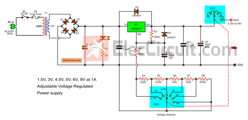
Resistor arrangement on LM317's does NOT adjust voltages as shown.
Refer to data sheet (carefully) - you need a variable resistor to local ground.
You can only use a second positive supply to form a negative one in the way that you are proposing if the "energy sources" are isolated relative to each other. eg two unconnected windings on the same transformer. The input of the "-ve" supply will be above ground voltage during operation.
To use a single transformer winding or non isolated sources what you want is to use an eg LM337 which is a less well known negative regulator equivalent to the LM317.
Here is a dual +ve & -ve supply circuit diagram using an LM317 and LM337. They use centre tapped transformer and a single bridge rectifier - but you could use the 2 separate windings as you propose and join them appropriately.
LM337 data sheet here
Add a small "spreading" resistor between rectifier output and 10 mF filter cap to widen the conduction angle. This reduces peak currents substantially and reduces RF noise generated by diodes and gives diodes a far less-hard time on conduction peaks.
I'd like to solder the smaller 500mA transformer onto the lugs of the larger transformer, is this safe/do I need to care about polarity?
Slightly unclear what is intended. Mechanically not wise.
Electrically - use wires.
Is it fine if I stack the two transformers on top of each other?
Probably. Minimal flux interactions with closed cores. Cooling may suffer slightly but easily judged and varies case by case.
If I had both outputs connected in series, would I be limited to 1A due to the second transformer only providing 500mA?
When done "properly" each supply can return its own Imax to ground. A current that starts at V+ and ends at V- will be limited by the smallest current capability.
I don't need that much current but I'm just curious if I'd run into trouble since the transformers are unbalanced. I have a 9V 15VA transformer as well, would that be better matched?
As above. As specified you can have 1A V+ to ground, 500 mA V- to ground or 500 mA V+ to V-.
What amperage of fuse should I use? I'm worried about magic smoke....
LM317 is self protecting within limits.
1A fuse fast blow blows at about 2A in moderate time.
How damaging would a shorted/max current output be on this circuit?
As above.
Best Answer
All PC PSU's started out with the intention of a minimum load sharing and so they used a common primary transformer coil and high mutual coupling so only one driver. They usually needed 10% preload on 5V to work at all 20 yrs ago. This was a major cost reduction.
Here in the fine print the specs are defined by Load Regulation error. 5V=1%, 12V=5% but with the other supply loaded with 60% and step load from 20% to 100%.
Your question needs a design load {Min:Max} as a spec for each channel and a tolerance.
It can be 5% if you like or 10% if you show what you are doing or 1% if you expecting too much. Just give the details and it can be sorted out.
This is also called crossload regulation error which is not given but can be figured out if you tell us what/why you need accuracy or low noise. This CLR error is often specified by better suppliers.
If you need 5% V tolerance on 12V from 20 to 100% step load, then the spec says you need 23W load out of 38.5W rated on the 5V rail. So you may need a dummy load. The less 5V load, the poorer tracking of 5V and 12V as a ratio from Pot adjust.