Let's say we have one 74HC595 and we want to light 16 leds (common anode) connected as a 4×4 matrix exactly as in the following picture :
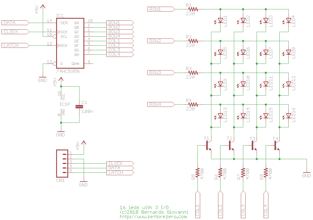
So, 4 first outputs to controls 4 rows.
The remaining 4 output to controls 4 columns.
From what I understand at this moment:
In the picture, there is a NPN transistor on the 4 columns to allow more current than what the 595 can sink.
Let's say only ROW1 is active, and all columns are active (LED1,LED2,LED3,LED4). Column 1, Column 2, Column 3 and Column 4 on the 595 will indicates a very low current, just the current set at the base of each transistor by the base current limiting resistor.
However, at ROW1, would it indicates at the 595 the sum of each led current of this row? So 80mA, if we assume each led at 20mA ?
If it's the case, in my case, there is much more 595 and much more leds and I don't want to operate near/over the 595 maximum current (75mA), would I simply add appropriate PNP transistors + base resistors to each ROW to reduce the current of each 595 rows pins ?
I want to keep the 74HC595 IC and low-cost single transistors. I know there are shift registers with higher current capacity and transistors-arrays IC that saves wires and resistors. Also that I can reduce the current of each led with higher resistors to keep it under 75mA, but I would like to understand how to properly work with a matrix arrangement that needs more than what the 595 can work with, using these simple components only.
In other words, is 4 PNP for rows and 4 NPN for columns, the best way to
handle >= 75mA on a single row ?
Best Answer
You can do it the way you suggest, however you should move the resistors to the NPN collectors, and you will need PNP (or emitter-follower NPN) transistors on each row output.
To get a rough idea of the current required- if 5mA is enough for the LED to be bright enough when supplied with DC you will have to supply 20mA for 1:4 multiplexing, and each row driver will have to source 80mA with a 25% duty cycle. Each column driver will have to sink 20mA with 100% duty cycle.