Check how much current your board needs. From memory, the ARM-USB-OCD can only supply a few 10's of milliamps. It is not uncommon for a dev board to use a couple of hundred. As a trouble shooting step, try getting openocd to communicate with the JTAG adapter without it connected to the board.
Yes, it is possible to turn an Arduino into an ARM JTAG adapter.
There are three problems, voltage, speed and drivers.
The Arduino natively runs at 5V. Most ARM microcontrollers are not 5V tolerant on their JTAG pins and require 3.3V. The easiest solution is to run your Arduino at 3.3V, failing that you will need some sort of level conversion (see I2C 3.3 to 5.0 V conversion for ideas).
The Arduino is connected to a PC via a serial link. I doubt it can feasibly go faster than 115200bps, which will make interactive activities like stepping through code in a debugger very slow. But, you'll be able to upload code and reflash devices.
JTAG is a high level protocol, specific to each processor family, which uses a SPI like interface to exchange data. Most JTAG dongles just provide a SPI interface over USB then leave the rest of the work to a PC application. OpenOCD and URJTag are popular choices. You will need a driver in one of these for your Arduino JTAG protocol.
The Bus Pirate is very similar to the Arduino (low speed microcontroller + FTDI chip). It supports JTAG with OpenOCD, so it's certainly possible.
If you use a Teensy/Opendous or other AVR-USB board, you could use eStick-JTAG.
But, for lost cost JTAG, I'd recommend one of the FTDI2232 based dongles. They're cheap and well supported by OpenOCD.

Best Answer
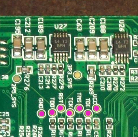
That isn't a standard JTAG pinout. If it is JTAG, though (which isn't a given), there are ways of mapping it out. For the sake of reference, let's number the pins:
Pin 8 is almost certainly ground -- it looks like it's connected to the ground plane.
Pins 3, 4, 5, and 6 look like they have resistors pulling them to ground. If I'm correct, this means they're inputs: they're likely to be some combination of TDI, TCK, TMS, and possibly TRST.
One of the remaining pins will be VCC. You should be able to find it by checking continuity to other known power nets on the board. Another one will be TDO; there's no obvious way to identify this one.
Beyond this, your best bet will be some combination of:
Look up the pinout of the CPU and map out continuity to known JTAG pins on the chip.
Guess a pin configuration, hook up a JTAG adapter, and see if it can pick anything up.
Use a software tool like JTAGenum to automate this guessing process.