Electronic – arduino – Schematic review

arduinomosfetschematicssolenoid

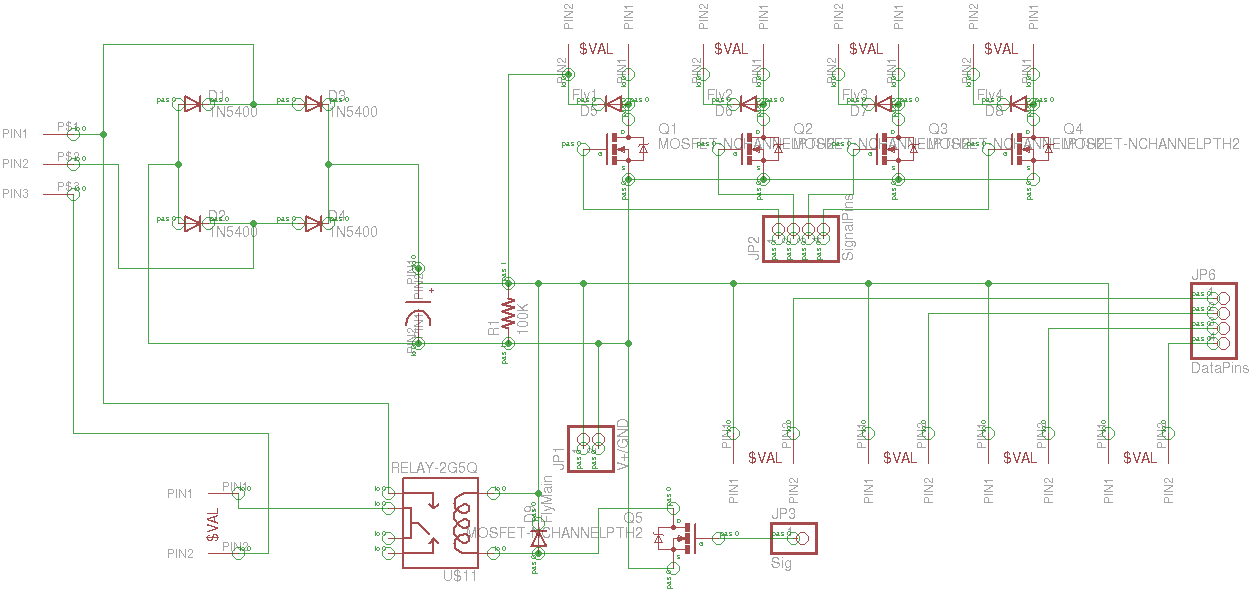
I'm designing a control circuit to operate a watering system. I've got a main inlet valve, four outlet valves, and soil moisture sensors in the mix, driven from a 25.4 V CT transformer. I was wondering if someone could review the schematic diagram. I have to make sure I didn't do anything outstandingly stupid, considering this is my first foray into controlling solenoids via MOSFETs / relays. Some explanation of the schematic is in order:

Upper left:

PIN1 is +12 VAC from the transformer

PIN2 is 0 VAC

PIN3 is -12 VAC

Lower left:

PIN1/PIN2 go to the main inlet valve, a 24 V solenoid valve.

The PIN1/PIN2 combinations across the top go to the outlet valves, all of which are 12 VDC solenoid valves.

The PIN1/PIN2 conbinations across the bottom go to the soil dampness sensors (simple soil moisture sensors made from plaster of paris and galvanized nails).

The data pins go to analog pins on the Arduino. Signal pins go to digital pins on the Arduino. The Arduino is powered from the V+/GND pins via its Vin pin.

enter image description here

Best Answer

  1. Schematic needs part numbers or a BOM attached. eg what type of cap?
  2. Card interface needs protection for ESD sensitive devices on interface pins such as MOSFET gates. or a warning label.
  3. Relay contacts may need ferrite filters to reduce ingress of signals from sprinkler wires (antennae) and internal electronics. CM ferrite choke recommended.
  4. Also contacts can create peak AC transients to be radiated from interface cables to nearby electronics connected to this card.
  5. Since these are not zero crossing switched solenoids, it is hard to say if there will be any EMC surge ingress issues at a system level but filtering or shielding may be necessary and use twisted pair wires. Otherwise, contacts may be heard on AM radio which you can use off channel as a quick test. concur with other suggestions.
  6. An LED indicator & resistor on board and each driver may be useful. 3mA or so should be adequate with any low cost AlGaAs indicator rated for 20mA.
  7. Schematic needs legible notes for interfacing requirements, test points
  8. Galavanized nails are highly unreliable for reliable plant moisture sensors but for crude watering, it may be acceptable. Capacitance mode is more reliable than resistive mode for linear thresholds due to drift in soil shrinkage around sensor, galvanic soil offset, AC hum, RF noise etc.. I hope you have done some research.

It is hard to read, but possible.