so to give a little bit of background, I want to experiment with led matrixes. I have multiple Arduino Nano boards, and have done small projects (9 LED bank with simple animations).
So I know that each pin can only supply a limited amount of current (perhaps 40mA).
So my test circuit of a 2*2 matrix has
P1, P2 for positive rows, and N1 and N2 for negative columns. All LEDs in row 1 have anodes wired together to P1, all cathodes in column 1 are wired together. also resistors are hard wired to each LED.
Now I there's plenty of current with a small matrix but if I get 9*9 LEDs I would definitely run out of current both onboard and per pin/row.
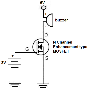
I successfully used this schematic to wire in a 2n7000 mosfet (200mA max) to P1. http://www.learningaboutelectronics.com/images/N-channel-MOSFET-switch-circuit.png
My own circuit looks somewhat like this rather hard to understand ascii diagram
    P1--*---*--
    ....l...l..
    P2--*---*--
    ....l...l..
    ....N1..N2
The dashes are anode wiring, the l's are cathode wiring and the N/P 1/2 are the header wires. (I plan to expand this to 4*4*4 so I want to be able to turn them all on without worrying about current limitations)
To clarify I set P1 HIGH, and N1 LOW to get the top-left led lit. I want 1 transistor per P (for positive, anode) wire, and one per N (negative, cathode)
So here's my question. Do I have to buy a P-channel mosfet in order to accomplish this? Or is there some way to do it with the 2n7000. (I bought 100pcs on eBay)
If I must buy P-channel transistors, can you provide a simple schematic and the equivalent to the 2n7000?
Thanks for reading and hopefully answering my post!
Best Answer
You do not need transistors on both rows and columns because, as @Milliways explained, you will not light all the rows and columns simultaneously. Since you already have a bunch of N-channel MOSFETs, and these are good for sinking current, you will put them on the columns (negative side of the LEDs). Now you can light a whole column at a time without worrying about current limitations. You do not need transistors on the rows, because at most one LED will be lit per row at any given time.
Your circuit will look like this:
And your code like this:
LOWHIGHto turn the LED on,LOWto keep it off)HIGH, this will turn the MOSFET on and light the LEDsLOW, this will turn off the whole columnHIGHLOW