I'm building a 5 V regulator for a PCB, and I was reading through the datasheet and Wikipedia to make sure I was doing it right.
What baffles me is that the regulator switches at 150 kHz. Yet most sources I've found online say the self-resonant frequency of your average electrolytic cap is below 100 kHz.
In the circuit on page 8 of the datasheet, there's a 220 µF electrolytic capacitor. Assuming 2 nH (low estimate) is a reasonable series inductance (is it?), then the highest possible resonant frequency should be
\$ f_c = \Large{\frac{1}{2\pi\sqrt{220e^{-6}\ F\ *\ 2e^{-9}\ H}}} = \small240\ kHz \$
So at 150 kHz the capacitor should barely be working as a capacitor. How does this even work? Why is it OK?
I did some simulations of the circuit to figure out what exactly was going on. I modeled the switch/diode as a 12 V square wave with duty cycle 5/12 = 0.417, and with a load of 5 ohm (for a 1 A current). The output capacitor is 220 µF, the inductor is 33 µH. First I made a Bode plot:
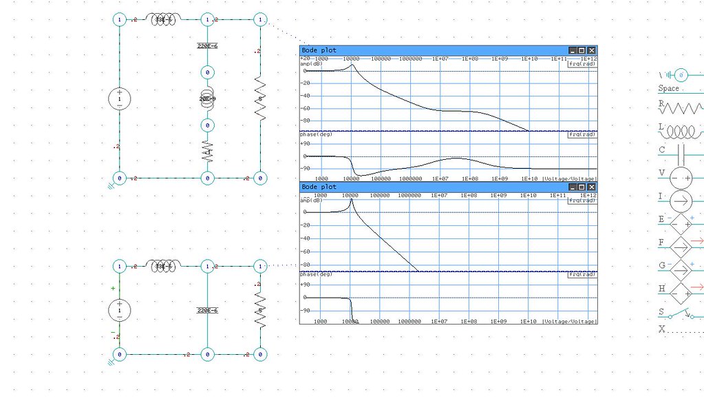
The bottom circuit is using an ideal capacitor (no ESL/ESR). It's basically a low-pass filter with a resonance at 11k radians (1.8 kHz). The top circuit is with an ESR of 100 mohm, ESL 20 µH. The ESR smooths things out at the resonant frequency. The ESL (self-resonant at about 75 kHz) causes the response to flatten out at around 75 kHz, and reduces the attenuation from -40 dB/decade to -20 db/decade.
And then I simulated it with SPICE:
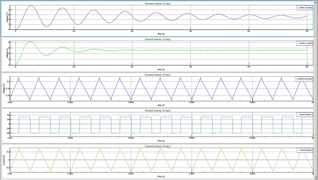
The top trace shows the ideal capacitor. Simulated over 3 ms, it rings at the resonant frequency of the filter (1.8 kHz).
The second trace shows the capacitor with parasitic effects included. It flattens out after a couple of milliseconds, although in the first millisecond the voltage shoots up to 9 V, and the current (not shown) peaks at 12 A, which might be a good reason to include some overvoltage protections.
The third trace shows the output voltage oscillating at around 5 V (also the voltage across the capacitor). The fourth trace is the instantaneous voltage across the series inductance. The fifth trace is the current through the capacitor.
So at these frequencies, the capacitor is indeed almost self-resonant. The impedance across it is almost entirely ESR (100 mohm). The impedance of the ideal capacitor part is 5 mohm; the impedance of the series inductance is 2 mohm (both negligible). But it still drinks up all the oscillatory current, because it is 0.1 ohm in parallel with a 5 ohm load. This is exactly what the capacitor is intended to do.
The fourth trace illustrates the effect of the series inductance. Across it is a mere 7 mV. The capacitor impedance contributes something similar. Out of 60 mV ripple, this is nothing — but if the frequency were higher, then the overall impedance of the non-ideal capacitor would be higher due to the parasitic inductance. You're fine until the impedance of the capacitor becomes a significant portion of the load — when that happens you get a large oscillatory current through the load, and that's bad.
This also illustrates the reason why the ESR is such an important parameter. If it's too low, then you don't damp out ringing of the LC circuit and your circuit has stability issues. But the higher it is, the more oscillations you'll get on your steady state voltage.

Best Answer
This paper describes the typical inductance and SRF of an electrolytic capacitor.
One way to really know what's going on is to hook the capacitor up to an impedance analyzer.
The difference in ESR between 100kHz and 150kHz is small (\$22 m\Omega\$ vs. \$25m\Omega\$). The minimum impedance is at around 70kHz.
Remember, for most forward-type switching power supply designs (i.e. buck) the size and number of output capacitors is much more influenced by the ESR you need to keep the output ripple within specification, not so much by the capacitance you need to maintain regulation when the power train isn't delivering energy - generally you wind up with much more C than you need need to get the ESR that you want.
Also, even when you exceed the SRF and the ESL becomes dominant, the part is still a capacitor - just with some inductance in series. The ESR (caused by ESL) has to become extremely huge before the part ceases functioning altogether as a capacitor, which will happen at extremely high frequencies (where the ESR approaches the load resistance). This article explains the concept very nicely.
(It's kind of like thinking about a gyrator circuit - it simulates inductance, but isn't really an inductor as it doesn't store energy in a magnetic field.)
Trust me, lots of power supplies operating at or above 100kHz are using electrolytic capacitors as output filters very successfully.