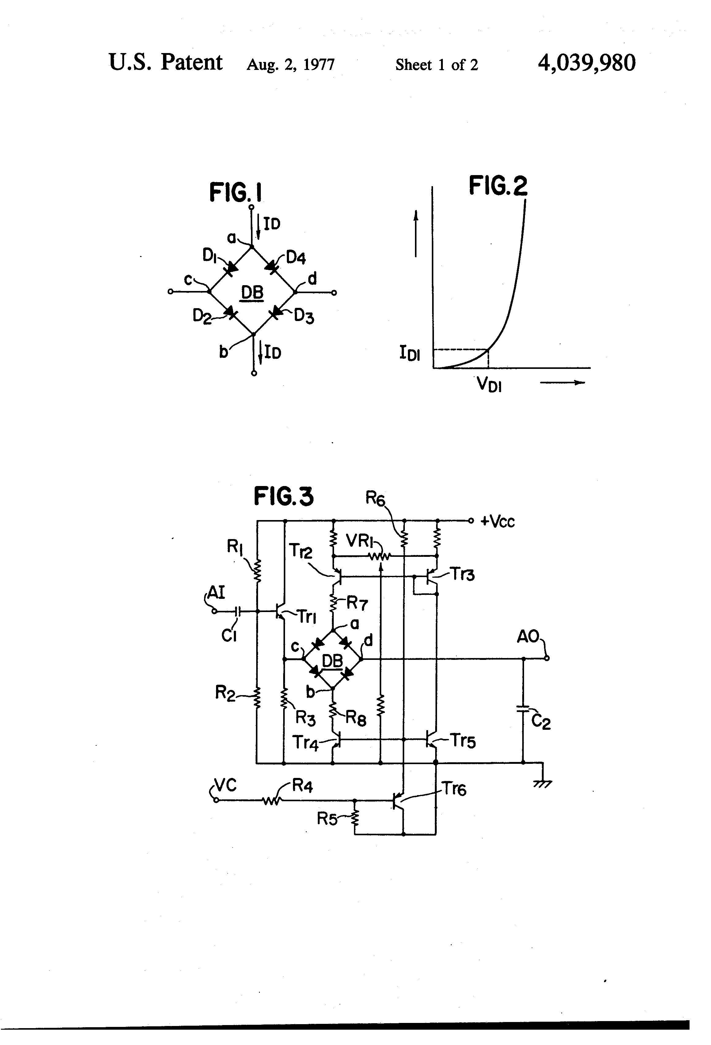
I'm investigating different analog low pass filter circuits and came across this Yamaha patent which ingeniously utilizes a diode bridge as a variable resistor. It takes some reading but in short: several transistors (Tr2-Tr5) act as a current source to provide a constant high impedance current to the diodes (from 'a' to 'b'). The relationship between the current through the diodes and the voltage across them results effectively in a resistance value. A signal is passed through the midpoints of the diode bridge ('c' and 'd') and and the effective resistance works with the capacitors impedance to filter out high frequencies in the signal. But having figured out how it works I'm not sure the current mirror/current source assemblage is really necessary. Could you not simply connect, say, Vcc to point 'a' and connect 'b' to ground? Couldn't you even leave in Tr4 between 'b' and ground and program it by sending a voltage to it's base?
Electronic – Controlling the current through a Diode Bridge VCF
bridgediodesfiltersynthesizer
Related Solutions
The main problem with a diode bridge is the fact that you always have two diodes in series with your circuit, and this creates a voltage drop of about 1.4 V between the power source and the load.
The power loss is simply this voltage drop multiplied by the load current.
It also means that you cannot connect the negative side of the load, which you might ordinarily consider to be "ground", to any external ground, which might be connected to either side of the power source.
In most cases, paralleling diodes is not a good idea. Their forward voltage drops Vf can be different, if they are not from the same batch. As a result one diode with the lowest Vf in the bank will conduct more current than the rest and more than it's rated for. That diode will get burned. Then the next one will get overcurrent in the same fashion. Untill all of the parallel diodes in the bank are burned. I'm afraid that the quote in the O.P. is describing this [wrong] approach.
But a bridge rectifier could lend itself to a possible workaround. Suppose, you've got 4x bridge rectifier ICs. You must assume that they are not from the same batch. But each of the diodes inside the bridge is from the same batch, because they are on the same die.

Notice that there are parallel diode connections within the bridges, but not between the bridges. No more than 2x bridges can be paralleled this way.
Proceed with caution. Best of all, just get a single bridge with sufficient current rating.
Related Topic
- Electronic – The flyback diode and its applications
- Electronic – Zener diode can vary current flow to maintain voltage drop, how does this magic effect work
- Electronic – Peak output current of a Full-Wave Bridge Peak Rectifier
- Electronic – Voltage Controlled Second Order Low Pass Filter
- Electronic – Why is the power supply terminal is not connected to ground in this bridge rectifier
- Electrical – half bridge smps with synchronous rectification basic working principle
- Electronic – Balance of current through oring diodes
- Diode capacitor circuit, what is the output across the diode
Best Answer
As a matter of fact current does not flow through the semiconductor diode but a mirror current exchanged at the depletion (P-N) region. The currrent in the depletion region changes the width thereof and hence its capacitance. Similar phenomenon means depletion region capacitance variation is also observed when the junction s reverse biased. Thus the junction capacitance is contrlled by the biasing voltage or current so the knee point of the filter. V T Ingole