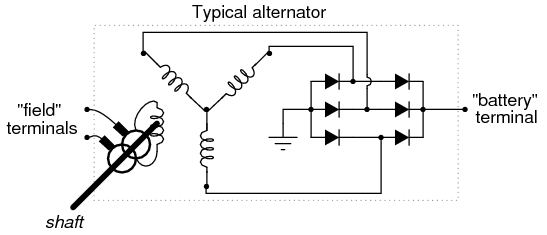
I am modeling a synchronous generator and in the stator circuit consisting of 3 phases at the alternator output, I have resistances and inductances of the end windings. Thus I have a 3D approximation of my current 2D approximation.
Now I am considering a generator with load. S = 50 kVA or 50 kW with p.f.unity. We have the formula $$Z = \frac{V^2}{S}$$
But which V to use? It is only after doing the simulations of the FE model that I get the output voltage V at the stator terminals. It's a chicken and egg situation. If I want to add an impedance or resistance for my loaded generator, I need to know V but V is only computed afterwards in the FE simulation.
The approximation which I can have is to use a V which I get from a no-load simulation and then use this V in the formula \$Z= V^2/S\$ to obtain the impedance Z to put in the stator circuit next to the end winding resistances and inductances in order to simulate a loaded generator.
As you can see, this is confusing to me. Looking forward for your comments. Thanks.
If I consider the voltage regulation formula, then I do not know my \$V_{rated}\$.


Best Answer
If you know the regulator equation with a transfer function of field current to output voltage and can model the effective series resistance , you can assume a starting point, knowing that no load is unstable by using 10% pre-load locally. Then switchover from stand-by to unknown load when system is in sync with grid. If no grid, then when up to speed switchover from standby load to external load.
Perhaps you can model the behavior for various initial loads and choose better assumptions for crossover speed with a known internal pre-load on startup, then you understand how to avoid overshoot with dynamic loads and passive loads. You also know that matching source impedance to load will help optimize power transfer.