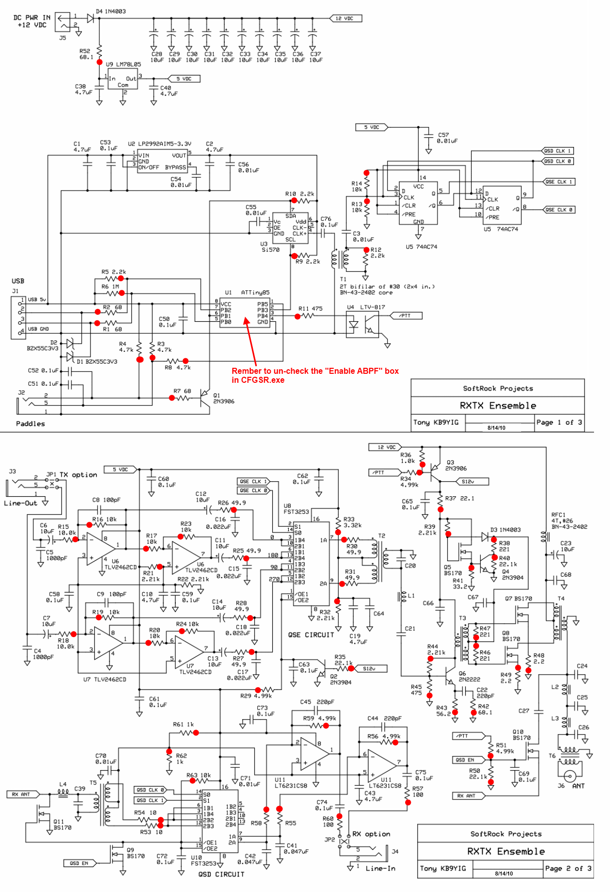
I've built a Softrock RXTX kit (full schematic: pdf gif, see lower-left corner). It has one connector for one antenna used for both receive and transmit, but I don't fully understand (likely due to my inexperience with RF design) what all the parts do. The full schematic is a mess, so I've done my best to transcribe the most relevant parts:

(source: circuitlab.com)
So, I understand that when \$\overline{PTT}\$ is low, then Q10 is off, which isolates the receiver. Q11 is on: why?
When \$\overline{PTT}\$ is high, Q11 is off, which is good, since I don't suppose we want to ground the receiver's input. How do we know that Q10 will be on, given that its source is floating?
What does C27 accomplish?
Say I had an RF amplifier and I wanted to add a similar circuit to bypass it when receiving. Would I have to worry about disturbing the impedance matching?
What should I consider when selecting the transistors to use? I intend to cover HF at least up to 30 MHz.

Best Answer
In your excerpted schematic, you left out the rest of the receiver input, which includes a DC path to ground through the coil L4 and the primary of the transformer T5. That's why you can assume the source of Q10 is at DC ground.
Depending on its value, C27 is probably there to provide an AC impedance that helps to isolate the switching circuitry from the low-pass filter in the transmit path (which is there to reduce harmonic emissions). It's a compromise between providing sufficient isolation while transmitting and providing sufficient signal when receiving.
Yes, you do need to pay attention to the impedance issues (see answer about C27 above). One of the things that C27 does is give you a more definite value of capacitance to incorporate into the design of the transmit path.
The main factors for transistor selection would be the peak voltage that it (Q10) can withstand when off, and the terminal-to-terminal capacitance, which, if too high, will limit the amount of isolation you can achieve. Note that you can't use a "power MOSFET" in this application; its body diode will conduct on the negative peaks and create problems.