Actually, this is a common thing to wonder.
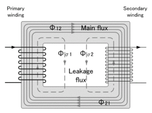
There is a dual to this. When you have devices sharing a common winding and magnetic flux(Magnetic "current") it makes a perfect dual for devices sharing a common electric conductor. Nice picture from wikipedia:
 2
2
You can also take a look at "Magnetic Circuits". You can start learning some fun terms when you go into these concepts in detail, like "Magnetic Capacitance," it seems that my flux does have capacitance.
The way you can determine how much energy passes through a transformer can be broken down into a magnetic circuit that works just like an electric circuit with different units. Magnetic Circuits are an analog of Electric Circuits, which are much easier to work with for many many reasons.
Think of it like a voltage source or a current source. They are direct analogs, but when you build a voltage source it is a hell of a lot easier than a current source.
Side Note
The magnetic flux is shared in a core due to the fact that magnetic flux is perpendicular to the wire, the issue with electric flux is that it points between two surfaces, not looped around. If it looped around a dielectric would get the job done.
In relation to the capacitor inside the other
IF the smaller becomes bigger, it will end up acting like two coupling capacitors with a series resistor between them, as it gets smaller, the overall electric field will be minimal, but you could put a big big E-Field in there, not nearly as effective as a transformer.
Just examining the 75 ohm and transformer connected to the 3k load, the combined impedance (assuming perfect transformers) is: -
75 ohms // (3k + 53.6 + 53.6) = 73.23 ohms
Clearly as you add more parallel transformers this number is going to drop so how do you account for the actual reading being a little higher: -
- The transformer dc winding resistances will add a little
- The tranformer leakage inductances will add a little impedance
Given what you have shown there can be no other reason other than your measurement accuracy is poor.

Best Answer
The gap they put between the two coils is the most important part.
The larger the gap, the less efficient your transformer will be due to magnetic fields that do not share between the coils. The larger the gap, the larger the isolation. This also stop arcing from high high voltage differences, it both puts a larger dielectric and increases the distance in the epsilon * A / d equation for capacitance. Make sure your coils have some sort of magnetic core to increase efficiency.
If you are really trying to keep capacitive coupling to a minimum by making sure the two devices have a shield between the coils. A shield grounded will stop them from capacitivly coupling to each other.
Secondly, some differential noise can couple through if you are working about differential noise, then you actually need to put a filter on the feed side, this will be a decent bit of work and probably not something you need to deal with.
Hope I helped, let me know if there is anything else I can help with.