First, you have to define what H parameters you want and exactly what they mean. The H parameters for transistors, for example, don't apply. Hfe stands for "H-forward-emitter" meaning the forward (input to output) characteristic in the common emitter configuration. Obviously that makes no sense for a opamp circuit like you show.
You show a opamp circuit, but ultimately this has only a single connection. Most H parameters don't make any sense for this since you can reduce this circuit to a Thevening voltage source, or equivalently, to a Norton current source.
H parameters are generally the ratio of two characteristics. You could make a case for specifying the H parameter looking backwards into the output (since that's all this circuit presents to the outside world). If you consider the output of this circuit to be a voltage, then this H-reverse parameter would the ratio of the change in output voltage to a small change in the output current. Note that this is in units of Ohms, and is exactly the Norton or Thevenin impedance of the single source this circuit is. This is why, again, it makes more sense to describe this circuit as a Thevenin or Norton source, depending on whether you view it as a voltage or current source, respectively.
You know the current through R4:
\$i_4 = \dfrac{A}{R_4}\$
Thus, you know the current through R3:
\$i_3 = i_4 \$
Thus, you know the output voltage of the 2nd op-amp:
\$v_{O2} = i_4(R_4 + R_3) = A(1 + \dfrac{R_3}{R_4})\$
Thus, you know the voltage across R2:
\$v_{R2} = A - v_{O2} = -A\dfrac{R_3}{R_4} \$
Thus, you know the current through R2 which is identical to the current through the capacitor:
\$i_C = i_{R2} = -\dfrac{A}{R_2}\dfrac{R_3}{R_4}\$
Now recall:
\$i_C = C \dfrac{dv_C}{dt}\$
Can you take it from here?
I can't find an error in my calcs, so I think I'm just
misinterpreting what Vs and Is actually are.
Switching to the phasor domain, we have:
\$I_c = -\dfrac{A}{R_2}\dfrac{R_3}{R_4} = j \omega C V_c\$
or
\$V_c = -\dfrac{A}{j \omega}\dfrac{R_3}{R_2R_4C}\$
Thus, the output voltage of the first op-amp is:
\$V_{o1} = A + V_c = A - \dfrac{A}{j \omega}\dfrac{R_3}{R_2R_4C}\$
And the voltage across R1 is:
\$V_{r1} = A - V_{o1} = \dfrac{A}{j \omega}\dfrac{R_3}{R_2R_4C}\$
Finally, the current through R1 is:
\$I_{r1} = \dfrac{V_{r1}}{R_1} = \dfrac{A}{j \omega}\dfrac{R_3}{R_1R_2R_4C} \$
But the source current is identical to \$I_{r1}\$, thus:
\$\dfrac{V_s}{I_s} = \dfrac{A}{I_{r1}} = j\omega \dfrac{R_1R_2R_4C}{R_3} = j \omega L_{eq} \$
Best Answer
Watch the video https://www.youtube.com/watch?reload=9&v=AEJtajaRj_s&feature=youtu.be&t=289
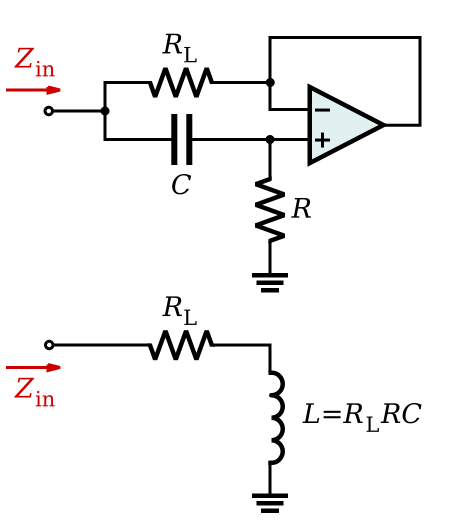
And here you have a floating inductor (gyrator)
simulate this circuit – Schematic created using CircuitLab