I am attempting to put a switch between the Data + and the ground wires in a USB cable. Now that I have cut open the USB cable, it does not seem to match any of the pinout diagrams I can find online.
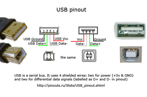
The next few statements are based on doing continuity tests on each wire with one probe connected to bare wire in the middle of the cable and the other probe in contact with the terminals on the USB connector. I am also using this pinout diagram to determine which terminal serves which function. http://pinouts.ru/visual/USB.jpg
So far, I have two separate red wires that each pass cont tests with the Vcc terminal, a white wire that passes cont with the Data+ terminal, a green wire that passes cont test with the Data- terminal. The 5th cable is not insulated, and passes cont test with the ground terminal.
My question is, is my ground wire useless now that I've cut open the braided insulation and foil sleeve that contained all 5 internal wires? Alternatively, is any of my methodology for testing this cable incorrect or do I seem to be missing a key bit of understanding?
Thanks
Best Answer
Non-insulated wire inside the USB cable is SHIELD. It should be isolated from BLACK ground wire in the cable, and connected only to metal shrouds of USB connectors. On a system level, the shields should be routed separately, and connected to signal/main ground at a single point via decoupling R-C network (0.1uF || 330R recommended), usually at the power supply feed point and Earth ground of the system (if any).