I need a split rail circuit for a 741 op amp.
The circuit can be found here:
or here (the latter can be simulated).
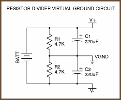
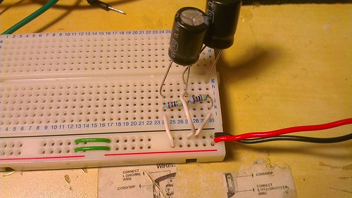
I have simulated the circuit in three different programs an it always seems to work. However, when I build the circuit on the breadboard, it doesn't work. With 9V DC supply instead of getting 4.5V, 0V and -4.5V I get 9V, 4.5V and 0V. It seems as if the caps weren't even in the circuit. I checked the polarity and the value of the caps and even used different ones. Still don't get any virtual ground, the circuit acts as a voltage divider. A photo of the breadboard circuit is here:
The circuit is damn simple, it puzzles me why it doesn't work. Again, I checked polarities, power, etc. Any help would be appreciated!
Best Answer
First of all, remove the center white wire from the breadboard. You're just shorting out half of the circuit with it.
Otherwise, it is working, you're just confused about where "ground" is. Connect the negative lead of your multimeter to the junction of the two capacitors. When you measure from there to the other end of each one, you'll see +4.5V on one, and -4.5V on the other.
Remember, "ground" is just a label for whichever node in the circuit you want to use as a reference. In this case, ground is not the negative lead of the battery.