I'm looking for help to upload from Arduino IDE into an ESP32-CAM module, without an FTDI programmer or shield.
Context
I've got a couple of ESP32-CAM modules with an associated ESP32-CAM-MB shield for programming via micro USB. Unfortunately the CH340-based programmer is not recognized by Windows. I know there are drivers around, but for security reasons I don't want to install random drivers downloaded from the Internet. I appreciate I'm maybe making my life harder here, but I'm strict about security, and I also like to learn.
The next popular option would be an FTDI programmer, but I'm afraid I'd end up in the same situation with missing drivers.
So my current strategy would be to use another board. I have some Arduino Uno R3 or ESP32-WROOM; I know the Arduino works so I'd like to try that one.
What I've tried
ESP32-CAM-MB shield
The shield doesn't show up in Device Manager in Windows.
Arduino UART
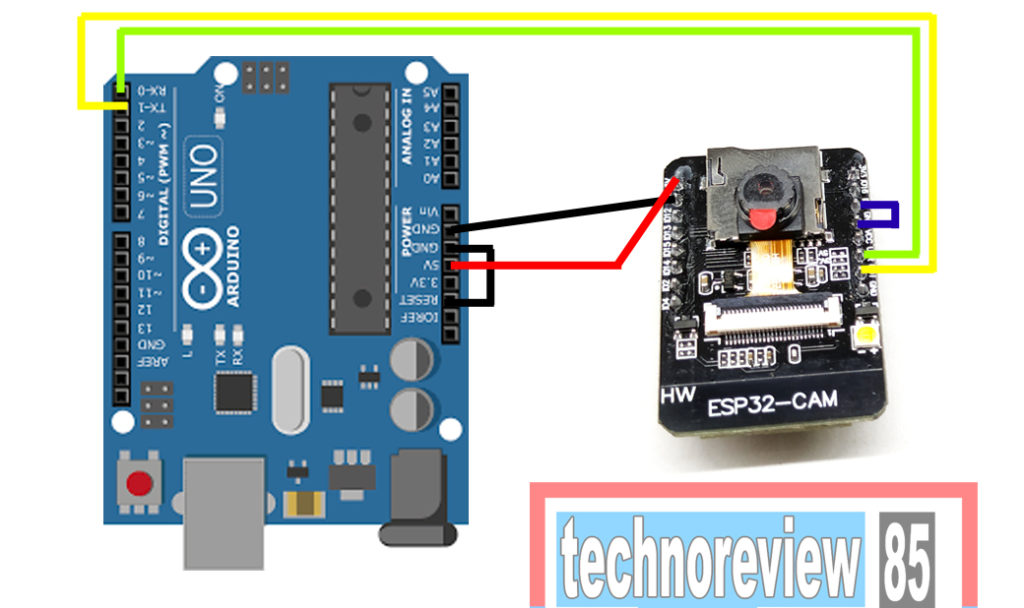
- Connect Arduino and ESP32-CAM: Tx->Rx and Rx->Tx, for Serial connection, and 5V and GND for power.
- Jumper on ESP32-CAM module between IO0 and GND to allow flashing.
- With or without jumper on Arduino RESET-GND, to pin Reset down, as I understand this may help prevent the Arduino from running. Although I'm not sure, I couldn't find any documentation about this.
Edit: Like this:
 .
.
Setting transfer rate to 115200 baud.
When trying in Arduino IDE, I get the same Connection timeout error (error 2). It seems nothing happens. I've tried pressing the Boot button too, without success.
I've looked at other questions here, and online tutorials, but in general either they cover generic UART transfer (not for programming), or they are very vague and don't explain why the steps are needed, which makes it hard to debug what goes wrong. In particular I couldn't find a single resource confirming that this setup is even possible, and how the Arduino will understand that it needs to forward what it receives from USB over to UART to the ESP32, but I saw several tutorials saying it "just works". So any help or hint, link at resources or docs, would be much appreciated.
Best Answer
The TXD pin on Arduino is MCU TXD out to RXD of PC.
You need to connect the TXD output of ESP32 to TXD pin of Arduino in order for the PC to receive data.
So connect TXD to TXD and RXD to RXD.
The UNO R3 has 1k protection resistors so connecting 5V logic output to 3.3V logic input should not do damage, but it is not ideal. The 5V logic input should detect 3.3V logic output properly as the R3 uses ATMega16U2 as USB serial adapter IC.