A few days ago I came across the source-code for this ATmega168 based Inductance Meter from Dan's Workshop Blog. Below is the code that I believe sets up an ATmega168 interrupt to measure an external frequency:
// set up the 16 bit timer as an external frequency counter:
TCCR1B |= (1 << CS10)|(1 << CS11)|(1 << CS12); // External clock, rising edge
TIMSK1 |= (1 << TOIE1); // Enable overflow interrupt,
                        // it will overflow a few times in counting frequency
I'm still studying how to set ATmegas interrupts, so I don't quite understand what that code does.
My questions are:
-
Does the code above determine which pin will provide the frequency to be measured? How?
-
Would that same code define the same input interrupt pin on an ATmega328?
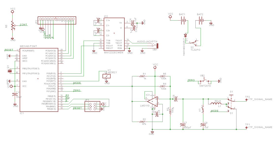
From the schematic posted on the site (copied below) I can see that the pin whose frequency is counted/measured is PD5 (pin 11 on the IC). Is that correct?

(source: dansworkshop.com)
Best Answer
No. Timer 1 is always clocked externally on T1, which is on PD5 on the 'XX8. If timer 0 was used instead then the external pin would be T0 (PD4), and so on. Setting CSn[2:1] to 0b11 merely selects the external input, and CSn0 selects the edge.
The '168 and '328 have the same peripherals and pinout, only the memory differs (hence the "8" at the end, with the varying powers of 2). But no pin directly triggers the interrupt; it is triggered from the timer, which is clocked via PD5.