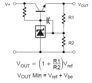
I'm working with the LM431, and have successfully observed it regulating voltage in a series pass configuration. The goal is to regulate an input voltage of up to 0-5V to a maximum output voltage of ~3.6V. Essentially, its the circuit shown on this EDABoard thread:

(source: elektroda.net)
http://www.edaboard.com/thread126488.html
The values are:
R1 = 1K
R2 = 2.43K
Rbase = 100 Ohms
Capacitor is not present on the cathode of the LM431 for the following trials (trying to eliminate as much as possible from the circuit to determine what is causing the current draw).
I've looked around for similar questions, and haven't seen much on the use of the 431 as a series regulator although you'll see this application in other 431 family datasheets, as [shown here][www.onsemi.com/pub/Collateral/TL431-D.PDF] . There are also other questions like this one which address the use of the 431 in a standard shunt scenario.
In testing, I've noticed that if I pull down the input of my circuit (collector of the BJT, or "V+" in the schematic above) through a resistor (1K) to ground, and apply a voltage to the output (emitter of the BJT, or "Vout" in the schematic above), I see a significant current into the reference pin of the 431. I disconnected R2 from the reference pin of the 431 so that there was no current from the output to ground through the reference divider network, and took the following measurements:
Vout (at BJT Emitter) | Iref (into reference pin on LM431) :
R1 = 1K, R2 = Infty, V+ = 0V
3.2V | 524 uA
2.8V | 420 uA
2V | 202 uA
1.5V | 486 uA
1V | 0 uA
From the datasheet, I thought that the maximum current into the LM431 reference was 4uA, and I am confused by what I am seeing. I tried a few different LM431 samples, and the same results occur.
Any insight into why the LM431 sinks so much current through the reference pin in this scenario?
EDIT – An NMOS FET between R1 and the reference pin will effectively shut off all current to the device, configured as follows:
Gate – Tied to V+
Drain – Tied to R1 (other side of R1 is at Vout)
Source – Tied to Vref
Hopefully this helps others trying to figure out how completely turn off an LM431 (or similar variants).
Best Answer
If I understand you correctly, in your test you essentially apply a voltage to the reference input, but leave the cathode open?
That's outside the Operating Conditions (p. 2, bottom), which require a minimum of Vref. So as far as the manufacturer is concerned, anything can happen.
What I think happens is that the reference input is now powering the chip via a (parasitic?) diode from reference to cathode.
The ~500uA you found matches the IZ(min) (minimum cathode current for regulation) or IZ(OFF) (off state current) in the table on page 3: 0.4 .. 1.0 mA.