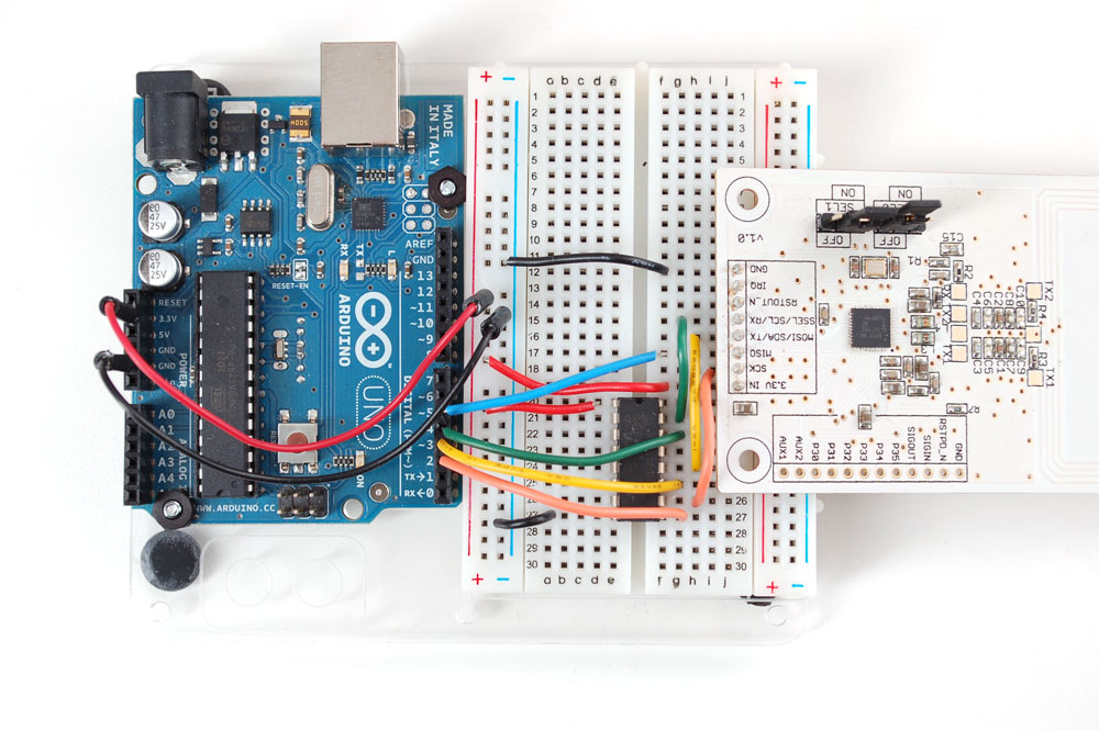
SETUP: I've put together a board comprised of:
- 24 V DC Supply voltage connected to 60 Ohm (10 W) Resistor that is in series with a LM7805C (5V Regulator). The LM7805C has a .33 uF cap on the Vin terminal, GND is connected to GND, and a 0.1 uF cap on the Vout terminal. When I measured my current coming out of this, I saw 400 mA (like I expected).
- Out of the LM7805C, I have an ATMega328PA that has a crystal oscillator connected to it and is connected to a Adafruit NFC board via SPI in the same way as this setup.
- The NI hex buffer (HEF4050B) you see is also attached to Vout of the LM7805 but using a resistive voltage divider, I "feed it" 3.3 V
- The Adafruit PN532 (NFC) board is connected also at Vout of the LM7805 and being supplied 5 V.
ISSUE: I'm currently facing a low current problem — there's not enough current flowing to the PN532 board — it requires about 150 mA to function appropriately, but when I put in my ATMega, my current drops to about 20 mA. Should I need to have a separate regulator for the PN532 and the 4050?
Schematic:
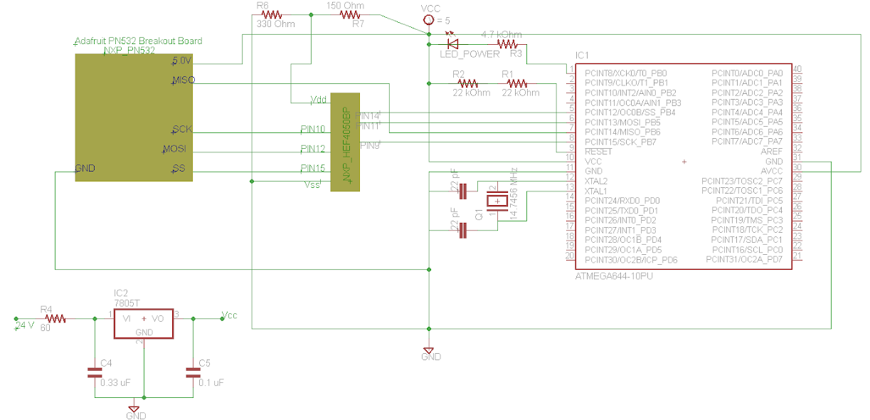
(click to view full size)
Best Answer
Using that series resistor would be a bad way to regulate voltage, but I assume you do this to keep the 7805 from dissipating too much. But 400 mA \$\times\$ 60 Ω is 24 V drop across that power resistor, so at 24 V input you won't have nothing left. Decrease the resistor value to maximum 35 Ω, then 400 mA will cause a 14 V drop, and you'll have enough left to feed the 7805, which needs 8 V in. If you expect more current to be drawn by your circuit you can calculate the resistor value as
\$ R_{MAX} = \dfrac{24 V - 8 V}{I_{MAX}} \$
But for the 4050 you use a voltage divider to get 3.3 V. Don't. The voltage will vary widely with the load, and you want you power supply to behave predictably, i.e. be rock steady. Use an LDO regulator to get your 3.3 V from the 5 V, like the MCP1700, which is cheap, and has a low ground current.
edit after you uploaded the schematic
A number of things are not quite clear to me. I couldn't find the schematic of the Adafruit breakout board, but it seems to be 5 V, then why do you need the HEF4050 buffer, and why do you use a 3.3 V supply for that, if both breakout board and AVR are 5 V? If the breakout board would run at 3.3 V, like when it has an LDO on board, then I would suggest to run the AVR on 3.3 V as well, so you won't have connection problems. If you need the 7805 for the breakout board you can use the MCP1700 I mentioned earlier to power the AVR from.
R1 and R2 don't seem to serve a function. You're not using the pin as reset pin (make sure you enable the internal reset), then program it as output, and you won't need a pull-up. (I don't see why you use two 22 kΩs here instead of one 47 kΩ either.)