I've built a NiMh battery charger (6-cell battery, 7.2v, 3000Mah) using DS2715.
Input is 12v.
Here is the schematic:

For Q1 I used IRF9540N
For Q3 I used IRLB8721PbF
L1 is a 47uF ferrite choke
R7 (current sense) is 0.1 Ohm
The diode is blinking and a current flowing to the battery is 0.75A which would indicate that the circuit is assembled correctly.
The problem is that Q1 is getting too hot (can't hold a finger on it for more than a second) even with a small heatsink.
I now it can handle up to 175C, but I thought that in a switching mode it shouldn't be hot.
I know that for linear mode it would need to dissipate (12v – 6v) * 0.75 = 4.5W of power, but in switching mode it shouldn't even need a heatsink.
Can someone help me understand what's going on here? Can I do something to make it cooler (apart from getting a bigger heatsink :))
Here is the datasheet for DS2715:
https://datasheets.maximintegrated.com/en/ds/DS2715.pdf
And here is the source of the schematic that I've used:
https://www.maximintegrated.com/en/app-notes/index.mvp/id/4180
Here is the layout of the thing:

Cheers!
Leonti
Update:
After using more appropriate mosfets overheating issue went away 🙂
IRLML2246TRPbF for Q1
FK3503010L for Q3
Accepted answer has the details
Best Answer
There are two important types of losses in a mosfet: Conduction losses and switching losses.
Conduction losses: This occurs when the mosfet is already switched on and is conducting current. You will have some resistance from drain to source. This resistance changes with the gate voltage. In this circuit, when Vch is pulled low, Vgs is about -4V. The resistance Rds will cause a small voltage drop. At 0.75A, for the Si2351DS you'll get Vds=0.075V, but for the IRF9540N it will be closer to Vds=0.4V. You get 0.3W loss just from conduction losses.
Switching losses: The gate of a mosfet acts as a small capacitor. While the gate charges, some current can flow trough the device, but there will still be a voltage drop across it. This is demonstrated in the following graph.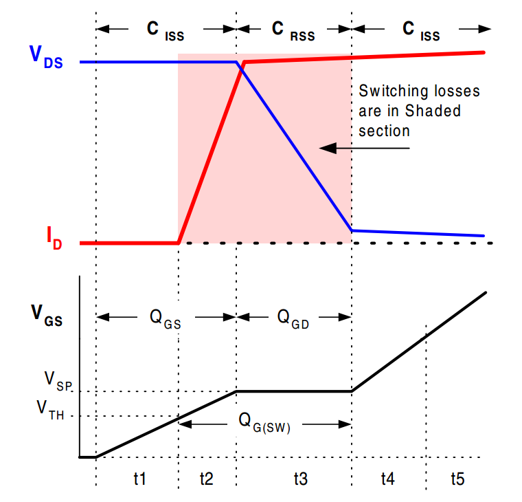 Switching losses also occur when switching the mosfet off.
For Q1: lets look at the input capacitance of the Si2351DS vs the IRF9540N, which is 250 vs 1300 pF respectively. It will take 5 times longer to charge the gate of the IRF9540N, so the switching losses increase. The same goes for Q3: 2sk3539 vs IRLB8721PbF (1077 vs 12 pF respectively.) In addition to this the IRLB8721PbF is fully switched on at a Vds of 6V whereas 2sk3539 is only requires 3V. This is important, because Q3 is used to accelerate the charging of the gate of Q1.
Switching losses also occur when switching the mosfet off.
For Q1: lets look at the input capacitance of the Si2351DS vs the IRF9540N, which is 250 vs 1300 pF respectively. It will take 5 times longer to charge the gate of the IRF9540N, so the switching losses increase. The same goes for Q3: 2sk3539 vs IRLB8721PbF (1077 vs 12 pF respectively.) In addition to this the IRLB8721PbF is fully switched on at a Vds of 6V whereas 2sk3539 is only requires 3V. This is important, because Q3 is used to accelerate the charging of the gate of Q1.
A good solution would be to use the same mosfets as used in the reference design or something comparable, not just any mosfet.
I hope this helps!
-kv