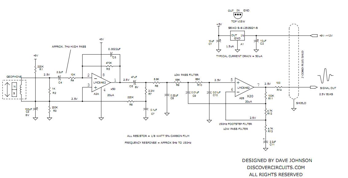
I'm working on building a seismometer using this geophone. I found a filtering and amplifying circuit as shown below:

More readable schematic here
Currently, I'm failing pretty hard at analyzing the circuit (really, really embarrassing considering I went to school for EE). There are some parts of the circuit where I am absolutely stumped.
-
The first thing I'm curious about is the "feed forward" circuit with C9 connected to R11. Why would there be a connection like this? Actually, I'm really confused as to why the feedback network in opamp 2 is the way it is (with that line of resistors and capacitor)
-
I'm not sure why the 2.2M resistor, R7 is there. I took this out of the circuit and found that there wasn't any effect to the circuit operation. I'm thinking that resistor is there for stability but stability for what?
-
Normally I would assume that the other lead for the geophone would be connected to ground but it instead connected to the 2.5 V line. I'm confused to why this is and I feel like it's a really obvious thing.
-
I want to confirm that because the op amps have a single supply, 2.5 V is applied to the noninverting input of opamp 1 (and inverting input of opamp 2) to provide a bias.
That's all the questions I have. The analysis seems really trivial and admittedly, I'm really just starting out in electronics. I've got to start reading the Horowitz-Hill book pronto!
Thanks for your help.
Best Answer
Try this, hopefully I haven't done my math wrong: -