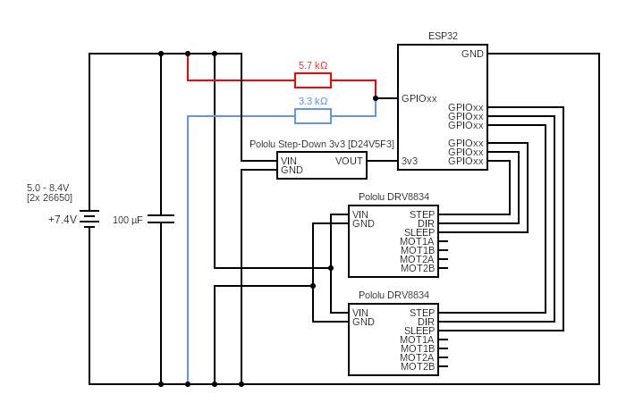
I'm trying to design a simple device based on ESP32 board, which will control stepper motors from a battery pack (26650 series).
I'm struggling with the battery level control part (red/blue colour on the diagram) and I'm not sure if I designed it correctly.
The 100uf capacitor marked on the diagram is a Aluminium Organic Polymer Capacitors 25V 100uF 20% ESR=40mOhms
Battery level resistors: Vishay
I'm aware that I should use a capacitor for the stepper drivers, but I'm not sure whether or not to use an additional capacitor for battery level readings?
Best Answer
If you really needed to save on power and you put the microprocessor to sleep, using a circuit with a p-ch mosfet could save power and not drain the battery while the microprocessor is sleeping. Otherwise a high impedance resistor divider would be appropriate.
Source: Low current battery monitoring
The ADC looks linear as shown below. I could not find any information on the impedance of the ADC an any of Expressif's documentation, so I'd assume that the impedance is low (100k worst case) and design around that.
Source: https://docs.espressif.com/projects/esp-idf/en/latest/hw-reference/index.html
Make sure you follow the ADC guidelines: