I have what I believe is a working buck converter design centered around the LM3485. It's intended to be a Raspberry Pi power supply.
The schematic is at Pi Power schematic, which I copy below.
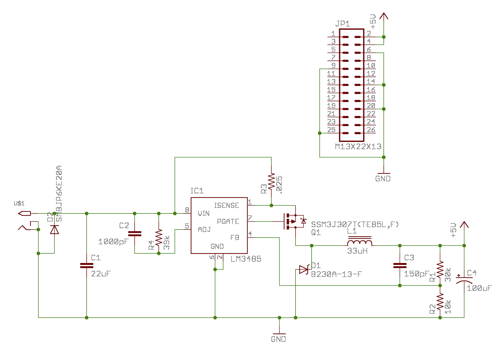
(note that in the image there are two errors: L1 is 15 µH instead of 33, and the MOSFET is a Si3443CDV in the latest version).
The parts selection came largely from an online TI design tool. I changed some of the values for availability and cost, and the resulting circuit seems to perform well on the bench.
But since I have some time before the first production boards come back, I've been going over and over the design with a fine toothed comb, and the one thing I can't quite work out is the selection of \$R_{adj}\$ – the current limiter comparator resistor.
According to the datasheet, the comparator compares \$V_{isense}\$ with \$V_{adj}\$, and when \$V_{isense}\$ is lower, it triggers the over-current shutdown.
Well, \$V_{isense}\$ is the voltage drop across a sense resistor, which for this design is 25 mΩ. The maximum rated current for the design is 2 amps, and the datasheet says the peak amps is \$(I_{max} + I_{ripple}) \times 1.1\$, and that for currents over 2 amps, \$I_{ripple} \le I_{out} \times 0.3\$.
On the \$R_{adj}\$ side, there is a calibrated 3.0 µA current sink that's connected on the opposite side of \$R_{adj}\$ from \$V_{in}\$.
Put it all together and the current limit should be
$$R_{adj} \times .000003 = I_{max} \times .025$$
or
$$R_{adj} = \frac{I_{max} \times .025}{.000003}$$
For an \$I_{max}\$ of 2.53A ( \$= 2.3 \times 1.1\$), \$R_{adj} = 22k\$ (roughly).
So why did TI's design software recommend 39k?
I have to assume TI is smarter than I am. What did I miss?
Best Answer
So I finally got around to actually testing this. It turns out that the current protection kicks in at around 4.25 amps with a 39 kΩ resistor. That squares with my calculations more than it does TI's.
I'm not sure at this point whether I want to leave the protection that high (the circuit is rated for only 2A) to accommodate surge capacity or reduce it. But that's another question for another day.