Let's get some terms straight first: An Ethernet interface is typically made from two parts: a MAC and a PHY. The MAC, Media Access Controller, handles all of the packet assembly, transmission, reception, and error checking. A PHY handles all of the PHYsical transport stuff like modulating the signal, managing the DC balancing, tracking baseband wander, etc.
There are some things that both sides do, to some extent. Both MAC and PHY do some level of data error detection. This is not redundant error detection, but just error detection that is related directly to the types of things that the MAC and PHY do. Also, both MAC and PHY are dependent on the packet nature of Ethernet. The MAC because it is using the packet nature to filter, route, and manage the data. The PHY because there are certain signal modulation/demodulation functions that require packets (and the space between packets) to function correctly.
The point is: You cannot get away from packets even if you just use the PHY. Of course, the packet headers do not have to be "standard" headers. And the CRC does not have to be a standard CRC. But you are still limited to the maximum packet length and inter-packet-gap that standard Ethernet requires. (Note: You might be able to do "jumbo" packets if both PHYs support it.)
There are many benefits to using standard Ethernet packet headers, however. We would refer to this as a "Layer 2" protocol. The main benefit is that you can use standard Ethernet switches to help connect different devices together.
You mention just connecting a "TDM stream" directly (more or less) to the PHY. Every time someone has said that to me they have been talking about running multi-channel digital audio over Ethernet. If that is the case then you have a bunch of other issues, like clock synchronization and error detection that will prevent you from doing it the easy way. I won't cover audio over Ethernet more in this answer, but tell me if that is what you want to do because I can add a lot more info in that case.
Historically there have been many products that have taken some sort of data stream and ran it over Cat-5 using Ethernet PHYs and FPGAs, but without traditional MACs. Some of them have used the proper Ethernet Layer 2 or Layer 3 packets, and some of them have not. Some have also used non-Ethernet technology like ATM or FDDI. Some of them have used FPGA's, but inside the FPGA is a more traditional CPU and MAC.
I hope that at this point you have realized that what you want to do (use an FPGA and PHY to transfer a data stream over Cat-5) is difficult. Not impossible, but difficult. Let me try to explain how difficult.
First, you will have to master FPGA logic design. Of all the professional FPGA logic designers I know of, this project is beyond the ability of maybe 95% of them. These are people who have been designing FPGAs for several years or even several decades. It will take you a long time to learn FPGAs enough to design this logic. Probably years if you are doing this as a hobby.
Next, you need to learn exactly what a MAC and PHY do, and how they interface. This is not as hard as learning FPGAs, but it isn't easy either. There are a lot of basic concepts that are important, but not easily learned.
Now you'll have to design a PCB to do all of this. Designing a reliable PCB that uses FPGAs, PHYs, and does all of the proper Ethernet signal integrity stuff is also not easy. Not super hard either. But on a scale of 1-10, with 1 being super easy, this PCB would be about a 6. Not hard for an experienced professional, but definitely hard for a non-professional-EE.
At this point you probably noticed that I didn't directly answer your questions. This was on purpose. I could answer your questions, but honestly that wouldn't help you. It would be like telling you how to build the second story of a house when you haven't figured out how to build the first story or even the foundation.
Start by learning everything about designing FPGAs that you can. Also learn everything about Ethernet that you can. There are lots of online resources from app notes, datasheets, and how-to's. Go to opencores.org and study their Ethernet MAC cores. Do this diligently and in a year you might be ready. And when you are ready then you will likely know the answers to 75% of your questions-- and you will be able to put the other 25% into proper context so when someone does give you an answer it will actually be useful to you.
If you don't need compatibility with ethernet, it doesn't matter which pair you use. It doesn't even really matter much that you use pairs.
Your main concern in this endeavor will be the resistance of the cables. You can find a chart of wire resistance and from that, calculate the total resistance of your cable. For an example, cat-5 cable is typically 24-26 AWG. From a table, I see that 100 feet of 23 AWG wire has a resistance of about \$3.2\Omega\$.
Say you want to move 500mA on this wire. We can calculate the power lost in the cable:
\$ P = I^2 R = (0.5A)^2 3.2\Omega = 0.8 W \$
or the voltage you will lose on this cable:
\$ V = IR = 0.5A \cdot 3.2\Omega = 1.6 V \$
Keep in mind, this is for 100 feet of wire, but since you need a supply and a return, the total length of the wire is twice the length of the cable.
This 0.8W is not only power not doing useful work, and less power available at your load, but also heat generated in the cable. A longer cable has more area to radiate heat, so can dissapate more power. This is why most tables also include a maximum current. \$500mA\$ is just a bit too much for 23 AWG cable.
Also, the voltage drop will reduce the ability of a voltage regulator to regulate the voltage on the other end. The voltage regulator has no way to know what the voltage on the other end is, so it can't regulate it.
Another concern is the maximum voltage the insulators in the cable can withstand. Power over ethernet provides 48V, so anything below this should be safe. Anything above that, consult the datasheet for your cable.

Best Answer
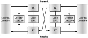
For the NIC card the loop back is a "mode" of operation, A properly designed NIC would deal with the collision detection appropriately, in full duplex, half duplex etc. situations.
I Think that your second item, "TX transmits to ..." is not right. I'd say that in loop back the TX transmits only to the RX channel and NOT to the connector/wire as that would defeat the intent of loopback testing. Likewise for your third item, the RX in loopback would only receive from the TX and not the wire also.