I need some help with this, I am a completely new to programing MCU's but I am trying my best to get this working and I could relay use some help. I am using the Sparkfun Basic 16×2 Character LCD along with a atmega32 MCU. Basically, the bottom row is full with black boxes and I cannot figure out why!
Here is my code:
/*
 * LCD.c
 *
 * Created: 11/29/2014 5:12:36 PM
 *  Author: John August
 */

#define F_CPU 16000000UL // 16 MHz clock speed
#include <avr/io.h>
#include <util/delay.h>

// Define LCD I/O Pins (8 Bit Mode)
#define LCD_PORT PORTD
#define LCD_PORT_DDR DDRD

// Define LCD Command Pins
#define LCD_CMD PORTC
#define LCD_CMD_DDR DDRC
#define RS PINC7 // Register Select
#define RW PINC6 // Read = 1 and Write = 0
#define EN PINC5 // Enable

void isBusy_LCD(void);
void Awaken_LCD(void);
void Send_CMD (unsigned char command);
void Send_CHAR (unsigned char character);

int main(void)
{
_delay_ms(50);
LCD_CMD_DDR |= 1<<RS | 1<<RW | EN<<1;
_delay_ms(50);

Send_CMD(0x01);  // Clear the screen 0x01 = 00000001
_delay_ms(50);
Send_CMD(0x38); // Put LCD in 8-bit mode
_delay_us(100);
Send_CMD(0b00001110); // Control Cursor
_delay_us(50);
Send_CHAR(0x41); // Display "A"

while(1)
{
}
}

// Check if the LCD is busy
void isBusy_LCD(void)
{
LCD_PORT_DDR = 0;
LCD_CMD |= 1<<RW;
LCD_CMD &= ~1<<RS;

while(LCD_PORT >= 0x80) //D7 is "HIGH" when busy, D7=0b1000000 (check read busy flag)
{
    Awaken_LCD();
}

LCD_PORT_DDR = 0xFF; // 0xFF = 0b11111111
}

void Awaken_LCD(void)
{
LCD_CMD |= 1<< EN;
asm volatile ("nop"); // asm = Inline low level assembler
asm volatile ("nop"); // "nop" = NoOperation (for delay)
LCD_CMD &= ~1<<EN;
}

// Send a command to the LCD
void Send_CMD (unsigned char command)
{
isBusy_LCD();
LCD_PORT = command;
LCD_CMD &= ~(1<<RW); // Set R/W to 0 (write)
LCD_CMD &= ~(1<<EN);  // Set Enable to 0
Awaken_LCD();
LCD_PORT = 0;
}

void Send_CHAR (unsigned char character)
{
isBusy_LCD();
LCD_PORT = character;
LCD_CMD &= ~(1<<RW);  // Set R/W to 0 (write)
LCD_CMD |=  (1<<RS);  // Set Enable to 1
Awaken_LCD();
LCD_PORT = 0;
}
I messed around with the V0 contrast pin, but adjustments will either turn the black boxes "transparent" or turn the whole screen full of black boxes. I think this is a code issue.
Here is a picture of the circuit:

Basically it follows this schematic. With the exception that I am using port C for RS, RW, and Enable. Port D is for DB0 through DB7 of the LCD.
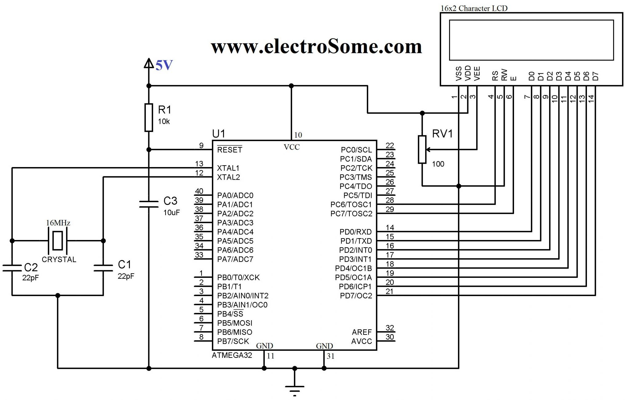
AVR        LCD
PC7-------> RS
PC6-------> RW
PC5-------> EN

PD0-------> DB0
PD1-------> DB1
PD2-------> DB2
PD3-------> DB3
PD4-------> DB4
PD5-------> DB5
PD6-------> DB6
PD7-------> DB7
Best Answer
Your initialization looks completely wrong. Check some HD44780 datasheet. There is always a follow path for 8-bit mode and 4-bit mode initialization. Remember that you are not allowed to check 'Busy Flag' during the first three operations of initialization.