I use the mega-isp solution mentioned above - the Arduino avrisp sketch is here
http://code.google.com/p/mega-isp/downloads/list
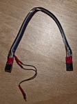
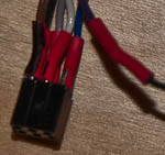
I do not use the shield they have - I made up a simple cable using two 6 pin dual-in-line header sockets to fit the programming ISP connector on your Arduino. (I did not have two dil sockets so I used standard single in line and superglued two 3 pin sockets together.
You then need a piece of ribbon cable or some wire.

Connect each pin on one socket the the corresponding one on the other, with the exception of pin 5 = Reset.
Connect one end of the cable to pin 5 - this is the end that will connect to the target AVR that you wish to program. Connect the other end of the pin 5 wire to a floating pin connector.
To use connect the cable to the arduino by placing over the ISP programming connector and connecting the floating lead to digital 10, connect the other end to the target ISP connector. You need to ensure that the pin 1's match up.
Program with avrdude using
avrdude -P com7 -p t2313 -c avrisp -b 19200 -U flash:w:fred.hex
where
com7 - the com port that the Arduino based programmer is on
t2313 - the type of AVR you wish to program (m328 for ATMega328).
fred.hex - the name of the hex file you wish to progam into the target.
I have used this to program Tiny2313 with no problems.
Note: The cable will carry 5v to power the target - if the target is already powered then do not connect pin 2 of the cable.
I was recently making a very similar serial programmer too, and had lots of problems with it.
First, check your crystal for the AVR. I can't see much on the photo, but its ground should be directly connected to power supply's ground. I've read that sometimes breadboards can make problems if the ground is connected through them because of impedance. Still, if you're programming a fresh AVR, it's going to be running on its own internal oscillator, if it has one.
Next step is to check if the AVR is getting correct voltage when connected to the programmer.
When you power on insert the AVR, check voltages on each pin and see in the datahseet what that pin is supposed to be. Some AVRs may need multiple ground connections and multiple voltage sources, especially if it has analog to digital converters.
Make sure that all your grounds are at same voltage. That may seem to be obvious, but I forgot to connect GND on my ATmega162 and even without GND, it managed to flash LED while running on internal oscillator.
I agree with starblue about capacitor. Read the datasheet for the AVR you're using and AVR Hardware Design Considerations document. It should provide some more information on proper decoupling.
Next step is to get a program which can tun on and off a pin on the serial port. You should use something like that to check if you have connected the programmer to the port you're attempting to use. Turn on a pin and check voltage on AVR socket. If you're not getting correct voltages, there's something wrong with your setup, so check everything again.
Now that I'm talking about setup, I noticed that there's nothing on Vs+ and Vs- pin of your MAX232. From a datasheet I'm reading, they should be connected to +8.5 V and -8.5 V and have 1 µF decoupling capacitors. On my setup, I connected one side of the capacitor to the pins and the other to +5 V and GND, since I didn't have needed voltages. I read that in a on-line tutorial, so I don't know if it's the best setup, but it works for me.
Do not expect the programmer to be detected by your computer. It doesn't communicate with computer at all! Instead, it just converts pulses which computer sends to what AVR can see. Also, there's no plug and play for most serial devices.
If you're still having problems, you'll need an oscilloscope to see what's happening. I didn't have one, so I took an audio cable, cut off one of its ends, placed a voltage divider there and connected the other end end to microphone input. There are numerous tutorials on the Internet on how to build the probe. Here's the one I used. I used Soundcard Scope to see the what kind of signal I'm getting. There should be a clock signal on the SCK and you should be getting signals on MOSI and MISO too. Reset should give you just a few signals, when the AVR needs to be reset.

Best Answer
I ran into something similar. It looks like it's a bug triggered by some combination of the OS, libUSB (in avrdude), and LUFA (the USB code in the programmer). This link might help: http://www.avrfreaks.net/index.php?name=PNphpBB2&file=printview&t=99674&start=0